Basement flood control system

a flood control and subterranean technology, applied in the direction of pump control, piston pump, non-positive displacement fluid engine, etc., can solve the problems of primary pump failure and often the greatest need

Inactive Publication Date: 2005-12-22
NIEDERMEYER KARL
View PDF9 Cites 65 Cited by
  • Summary
  • Abstract
  • Description
  • Claims
  • Application Information

AI Technical Summary

Benefits of technology

[0005] The invention is directed to a basement flood control system for use in a structure having a basement floor below ground level and having a sump pit or collection basin for gathering subterranean water for removal from the structure. The system comprises two primary pump units which are operated with line current and a battery-operated backup pump unit. A sensor arrangement is provided for sensing water level in the collection basin. A controller is connected to the sensor arrangement and the pump units for variously activating the pump units singly or in any combination responsive to input received from the sensor arrangement.

Problems solved by technology

A typical sump pump operates using line power, but its need is often greatest when storms occur.
Also, inevitably the primary pump will ultimately fail.

Method used


Image

  • Basement flood control system
  • Basement flood control system
  • Basement flood control system

Examples


Embodiment Construction

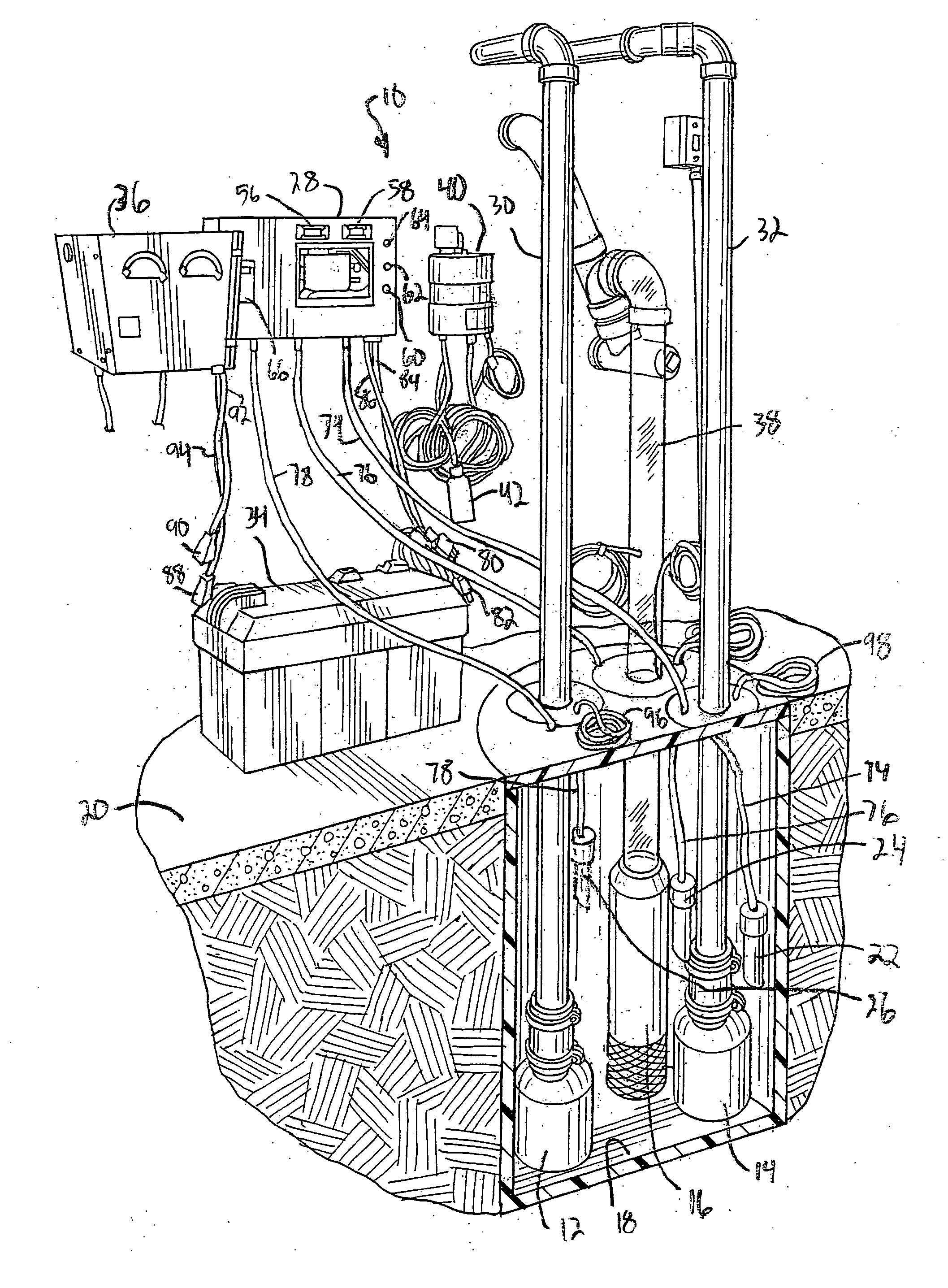
[0016] A basement flood control system according to the invention is illustrated generally at 10 in FIG. 1. The basement flood control system includes, as primary components, two primary pump units 12 and 14 operated with line current, and a battery-operated back-up pump unit 16. The three pump units 12 through 16 are installed in a collection basin 18, such as a typical sump pit which, as illustrated, is installed in a basement floor 20 or the like at a subterranean location so that ground water can be collected in the collection basin and removed.

[0017] The basement flood control system 10 also includes a sensor arrangement for sensing water level in the collection basin 18. The sensor arrangement comprises a plurality of sensor elements, each of which preferably comprises a sensor tube 22, 24 and 26 which is suspended at a different elevation at the collection basin 18.

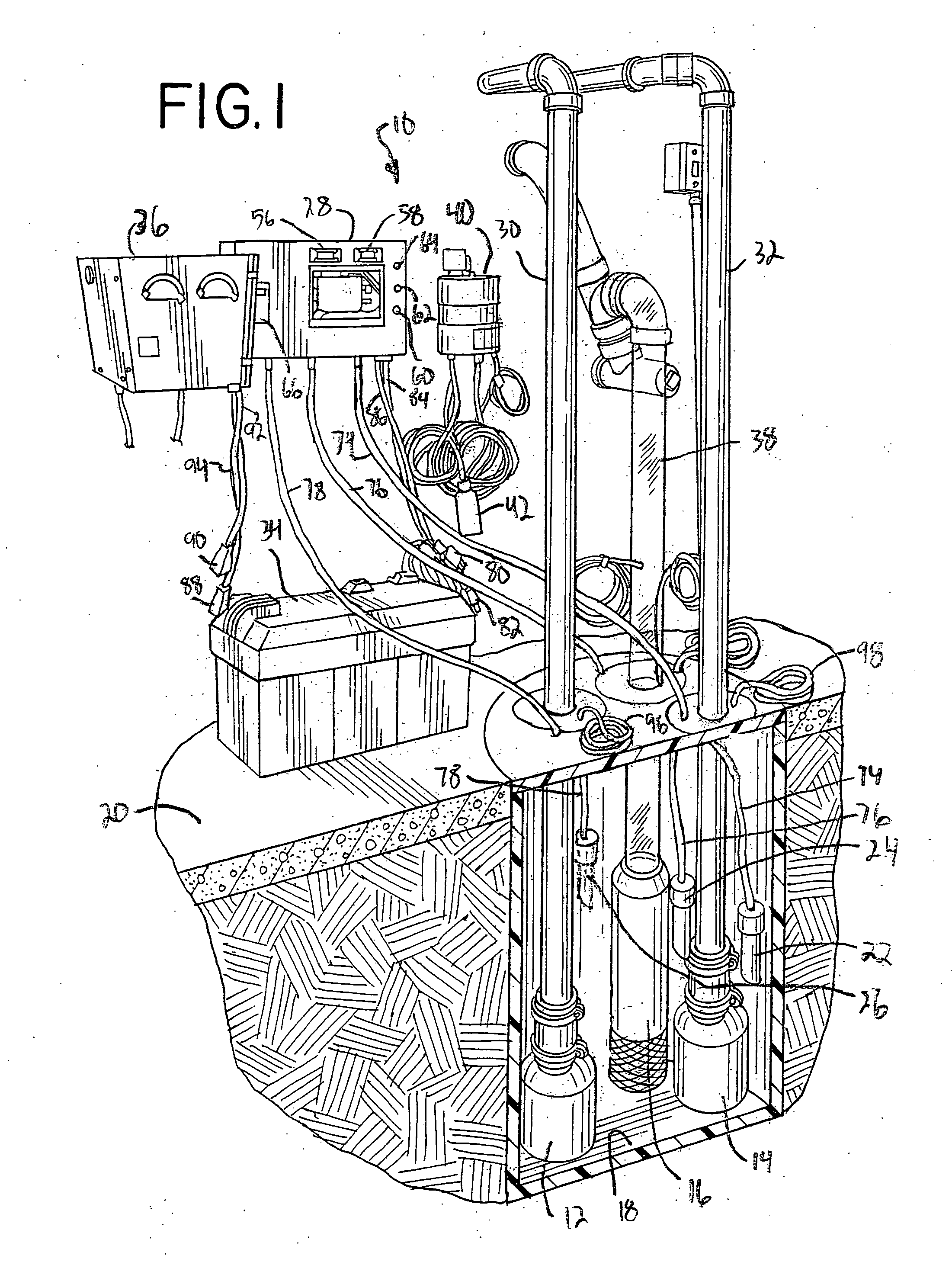
[0018] A controller 28 is connected to the sensor arrangement 22 through 26 and the pump units 12 through 16 f...


PUM


Abstract

A basement flood control system for use in a structure having a basement floor located below ground level and having a sump pit or other collection basin for gathering subterranean water. The system has two primary pump units operated with line current, a battery-operated back-up pump unit, and a sensor arrangement for sensing water level in the collection basin. A controller is connected to the sensor arrangement and the pump units for variously activating the pump units singly or in any combination responsive to the water level detected by the sensor arrangement.

Description

BACKGROUND OF THE INVENTION [0001] This invention relates to control of subterranean water, and is particularly suitable as a basement flood control system for use in a structure having a basement floor below ground level which must be kept free of the ingress of subterranean water. [0002] In structures, such as homes, having basements which extend below ground level, it is imperative that the ingress of water be prevented so that the basement space may be usable. To that end, structures typically have footing drains leading to a sump pit or other similar collection basin, from which water is removed via a sump pump. The sump pump of applicant's U.S. Pat. No. 4,461,614 is a typical example. [0003] A typical sump pump operates using line power, but its need is often greatest when storms occur. At that time, line power can be lost, and a well-provided home also has a battery-operated emergency pump unit in case power to the house is lost so that pumping can continue and avoid basement...

Claims


Application Information

Patent Timeline
Patent Type & Authority Applications(United States)
IPC IPC(8): F04B17/00F04B35/04F04D15/02
CPCF04D15/029
Inventor NIEDERMEYER, KARL
Owner NIEDERMEYER KARL
Why Eureka
Try Eureka