Multi-axial bone attachment assembly

a bone screw and multi-axial technology, applied in the field of orthopaedic implants, can solve the problem of impracticality of the degree of precision required to use such an inflexible device, and achieve the effect of increasing the allowable angulation of the bone screw

Active Publication Date: 2005-12-22
WARSAW ORTHOPEDIC INC
View PDF49 Cites 297 Cited by
  • Summary
  • Abstract
  • Description
  • Claims
  • Application Information

AI Technical Summary

Benefits of technology

[0007] One embodiment of the present invention is a unique multi-axial bone attachment assembly that includes a saddle member and a bone anchoring member. The saddle member has a plurality of upright portions that define a channel through the saddle member. The saddle member further has a hole therethrough bounded by an inner wall, and the hole forms a lower opening in the saddle member. The lower opening in the saddle member may contain angular cutouts placed symmetrically about the axis of the saddle to increase the allowable angulation of the bone screw in relationship to the axis of the saddle. The position, angle and number of cutouts may vary as required by the application of the multi-axial bone attachment assembly. The bone-anchoring member extends through the opening. The bone-anchoring member includes a head portion and an anchoring portion. A further embodiment of the present invention includes a washer (crown member). The washer may have a recessed portion for accommodating an orthopedic rod and may include a radially extending projection. The washer is fitted within the hole of the saddle member and atop the bone-anchoring member.

Problems solved by technology

While useful in certain circumstances, in many therapeutic situations the degree of precision required to use such an inflexible device is impractical.

Method used


Image

  • Multi-axial bone attachment assembly
  • Multi-axial bone attachment assembly
  • Multi-axial bone attachment assembly

Examples


Embodiment Construction

[0037] Reference will now be made to the embodiments illustrated in the drawings and specific language will be used to describe the same. It will nevertheless be understood that no limitation of the scope of the invention is thereby intended, such alterations and further modifications in the illustrated device, and such further applications of the principles of embodiments of the invention as illustrated therein, being contemplated as would normally occur to one skilled in the art to which the invention relates.

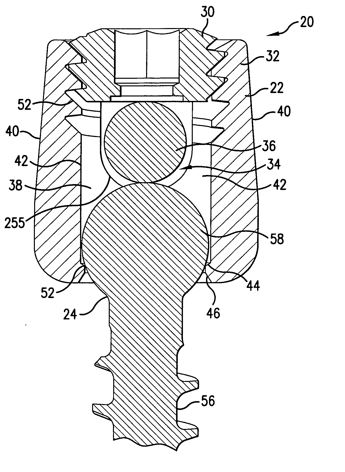
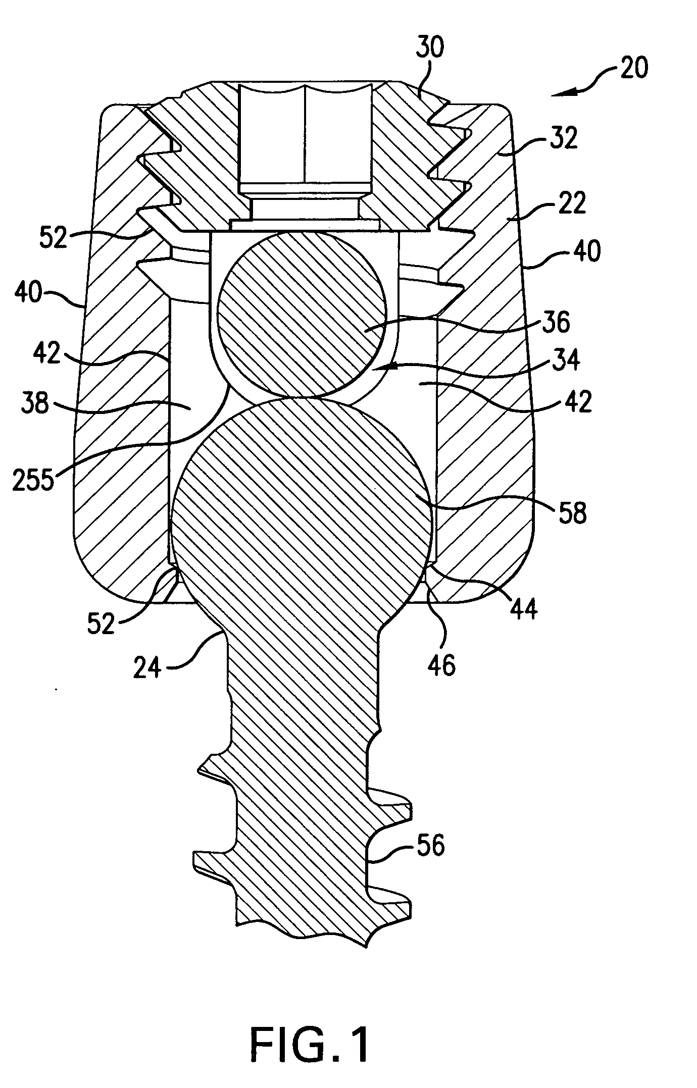
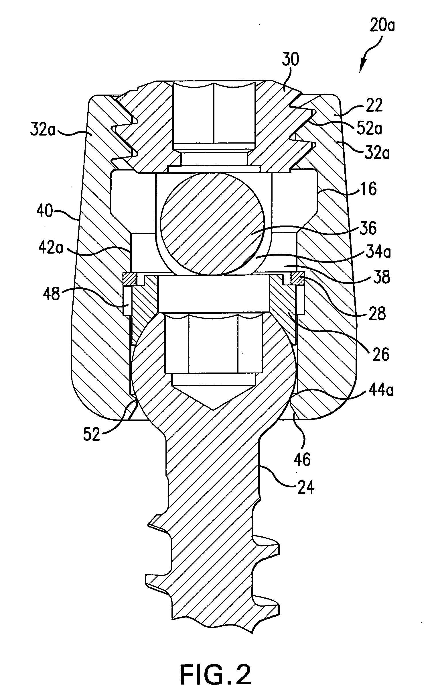
[0038] In FIG. 1, there is shown an embodiment of a multi-axial bone anchor assembly 20. Bone anchor assembly 20 includes a saddle member 22, a bone anchoring member 24, and set screw member 30. Saddle member 22 generally has a U-shape, with two upright portions 32 defining a channel 34 extending through saddle member 22. Channel 34 is then configured to accommodate an elongated member 36, such as a spinal rod. For posterior cervical fixation, rod 36 may have one of a number...


PUM


Abstract

A posterior fixation system includes a saddle member and an anchoring member. The anchoring member anchors the saddle member to bone. The saddle member includes a pair of upright portions that define a channel. The saddle member further has a hole therethrough bounded by an inner wall, and the hole forms a lower opening in the saddle member. The lower opening in the saddle member may contain angular cutouts placed symmetrically about the axis of the saddle to increase the allowable angulation of the bone screw in relationship to the axis of the saddle. The channel is adapted to receive an orthopedic rod, and the hole in the saddle member is adapted to receive the anchoring member. The saddle member and the anchoring member can be coupled so as to allow multi-axial movement of the members.

Description

BACKGROUND OF THE INVENTION [0001] The present invention generally relates to orthopedic implants used for correction of spinal injuries or deformities, and more specifically, but not exclusively, concerns apparatuses for fixing a portion of the spine, such as the cervical spine, to allow correction or healing thereof. [0002] In the field of spinal surgery, it is known to place implants into vertebrae for a number of reasons, including (a) correcting an abnormal curvature of the spine, including a scoliotic curvature, (b) to maintain appropriate spacing and provide support to broken or otherwise injured vertebrae, and (c) perform other therapies on the spinal column. [0003] Typical implant systems utilize a rod as the support and stabilizing member. In such an implant, a series of two or more screws are inserted into two or more vertebrae to be instrumented. A rod is then placed within or coupled to the heads of the screws, or is placed within a connecting device that links the rod ...

Claims


Application Information

Patent Timeline
Patent Type & Authority Applications(United States)
IPC IPC(8): A61B17/70A61B19/00
CPCA61B17/7032A61B2019/305A61B17/7038A61B17/7037A61B2090/035A61B17/70
Inventor COATES, BRADLEY J.FARRIS, ROBERT A.TAYLOR, HAROLD SPARRPOYNER, JEFFREY WADE
Owner WARSAW ORTHOPEDIC INC
Why Eureka
Try Eureka