Control device for four-wheel drive vehicle

a control device and four-wheel drive technology, applied in the direction of braking systems, process and machine control, instruments, etc., can solve problems such as vehicle destabilization, and achieve the effect of low maximum braking for

Inactive Publication Date: 2005-12-29
SUBARU CORP
View PDF4 Cites 28 Cited by
  • Summary
  • Abstract
  • Description
  • Claims
  • Application Information

AI Technical Summary

Benefits of technology

[0008] According to the control device for the four-wheel drive vehicle, the low maximum braking force and the destabilization of

Problems solved by technology

However, the electrically-driven parking brake brakes only the rear wheels, and thus the maximum generab

Method used


Image

  • Control device for four-wheel drive vehicle
  • Control device for four-wheel drive vehicle
  • Control device for four-wheel drive vehicle

Examples


Embodiment Construction

[0011] A preferred embodiment according to the present invention will be described hereunder with reference to the drawings.

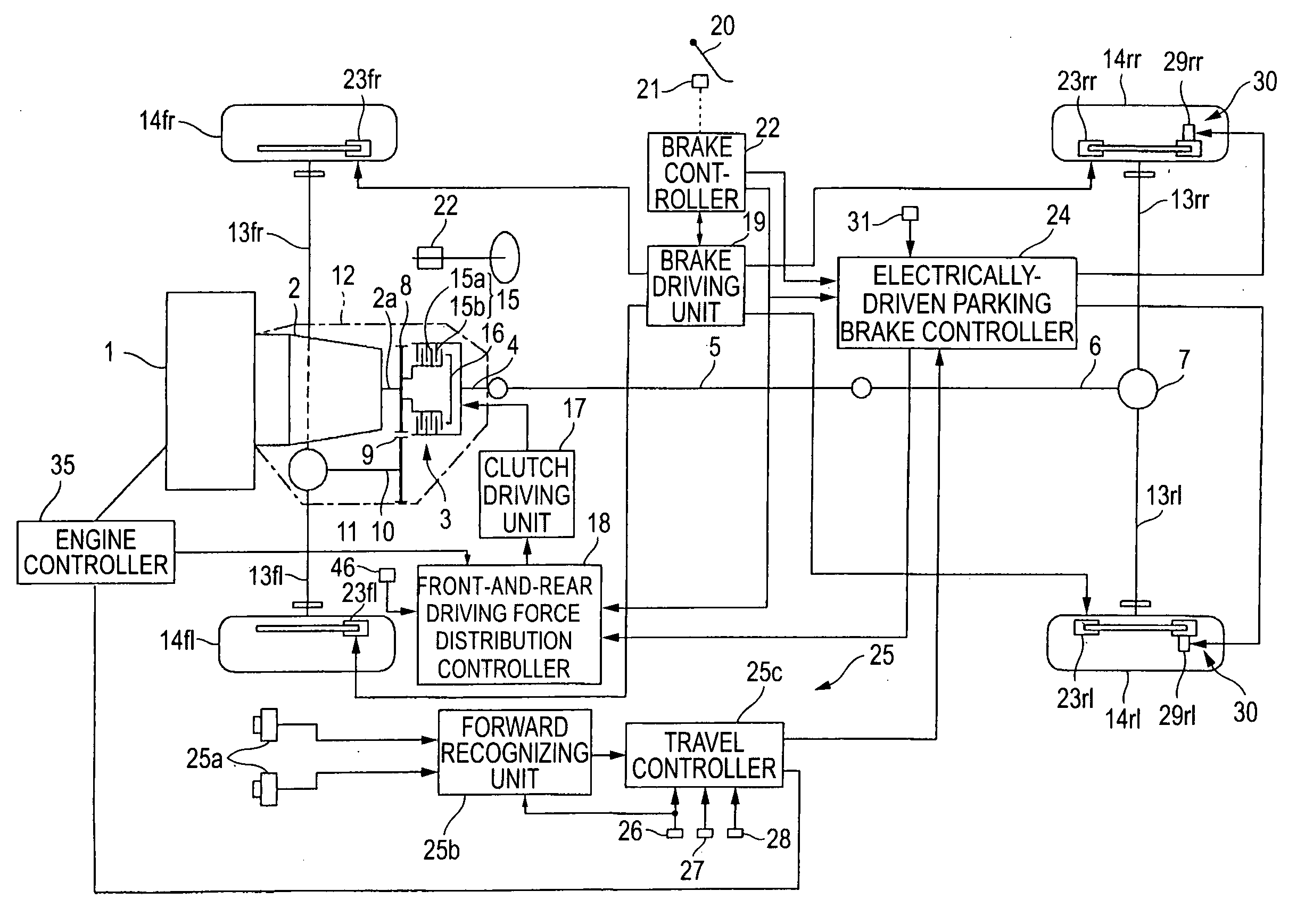
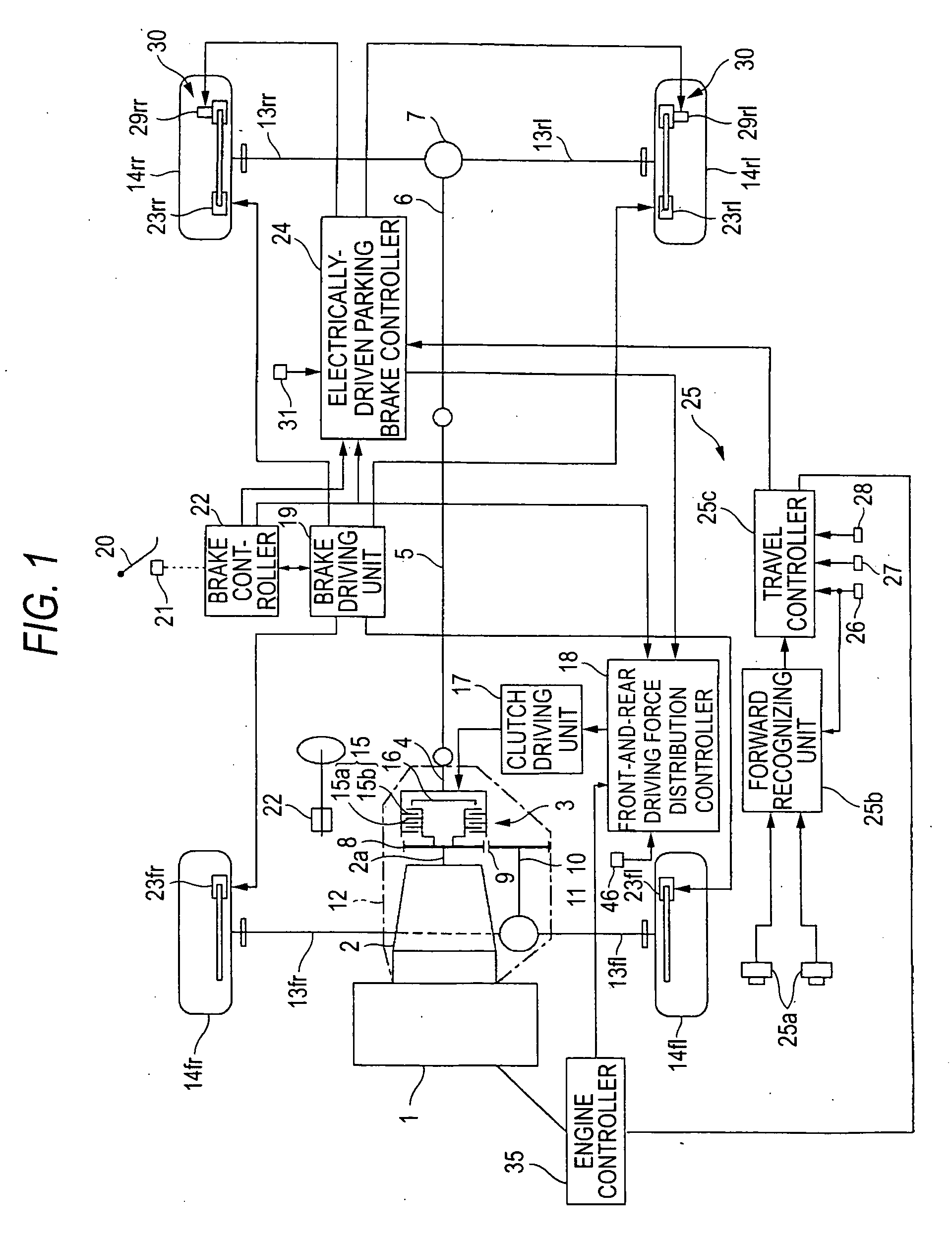
[0012] In FIG. 1, reference numeral 1 represents an engine disposed at the front side of the vehicle, and the driving force of the engine 1 is transmitted from an automatic transmission (illustrated as containing a torque converter, etc.) 2 at the rear side of the engine 1 through the output shaft 2a of the transmission to a transfer 3.

[0013] Furthermore, the driving force transmitted to the transfer 3 is input to a rear-wheel final reduction gear 7 through a rear drive shaft 4, a propeller shaft 5 and a drive pinion shaft unit 6, and also input to a front-wheel final reduction gear 11 through a reduction drive gear 8, a reduction driven gear 9 and a front drive shaft 10 serving as a drive pinion shaft unit. Here, the automatic transmission 2, the transfer 3, the front-wheel final reduction gear 11, etc. are integrally provided in a case 12.

[0014] Furthermor...


PUM


Abstract

When supplied with a signal for correcting a vehicle behavior is input from a brake controller, an electrically-driven parking brake controller releases actuation of an electrically-driven parking brake when the electrically-driven parking brake is actuated. When supplied with a brake control amount when abnormality occurs in a main brake system is input the electrically-driven parking brake controller drives electric motors to generate the brake control amount concerned. Furthermore, when supplied with the brake control amount of the electrically-driven parking brake 30 from an ACC system, the electrically-driven parking brake controller drives the electric motors to generate the brake control amount concerned. The front-and-rear driving force distribution controller directly couples the front shaft and the rear shaft when the electrically-driven parking brake is actuated.

Description

BACKGROUND OF THE INVENTION [0001] 1. Field of the Invention [0002] The present invention relates to a control device for a four-wheel drive (All-Wheel-Drive) vehicle that has an electrically-driven parking brake for braking the rear wheels and freely distributes the driving force among the front and rear wheels. [0003] 2. Description of the Related Art [0004] An electrically-driven parking brake which is actuated by an electrically-driven motor has been developed and practically used a sparking brakes for vehicles. JP-A-7-89420 discloses one of these electrically-driven parking brakes. According to JP-A-7-89420, the electrically-driven parking brake comprises a cylinder formed in a caliper, a freely-slidable piston disposed in the cylinder, a screw shaft for reciprocating the piston to a disc, a motor for actuating the screw shaft, a measuring mechanism that is provided to the screw shaft and controls the shift amount of the piston by brake press force occurring to the piston, and ...

Claims


Application Information

Patent Timeline
IPC IPC(8): B60K17/348B60K31/00B60T7/12B60T8/00B60T8/1755B60T8/1769B60T13/74B60T17/18B60W10/02B60W10/18B60W10/192F02D29/02
CPCB60T13/74B60T8/1769
Inventor TSUKASAKI, YUICHIRO
Owner SUBARU CORP
Why Eureka
Try Eureka