Monitoring apparatus

a monitoring apparatus and a technology of a camera are applied in the field of imaging apparatus, method and program, which can solve the problems of inability to find intruders, inconvenient operation, and inability to change the area, so as to efficiently and reliably photograph any intruder

Inactive Publication Date: 2005-12-29
SONY CORP
View PDF14 Cites 30 Cited by
  • Summary
  • Abstract
  • Description
  • Claims
  • Application Information

AI Technical Summary

Benefits of technology

[0007] Assume a monitor camera is installed in an area which unauthorized persons are forbidden to e

Problems solved by technology

Tremendous labor and time are required.
In addition, changes in the area may be overlooked because this system depends on the eyes of the watchman.
When the area is monitored at night, the watchman cannot help but try to find intruders, if any, from the

Method used


Image

  • Monitoring apparatus
  • Monitoring apparatus
  • Monitoring apparatus

Examples


Embodiment Construction

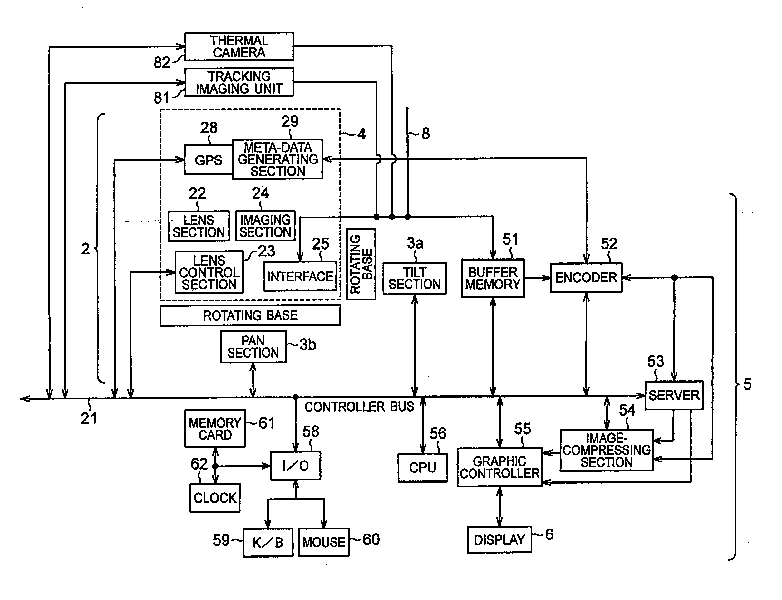
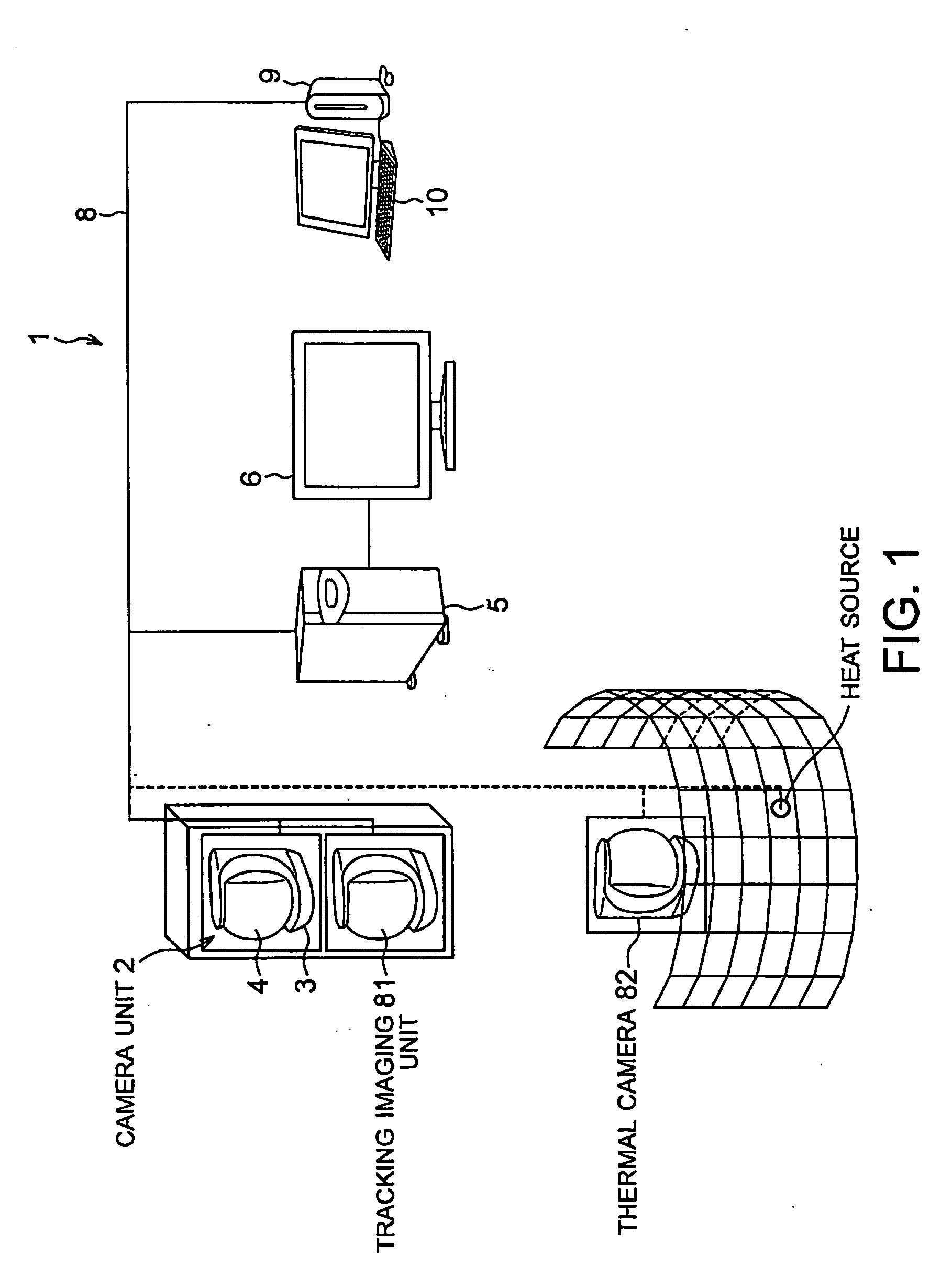
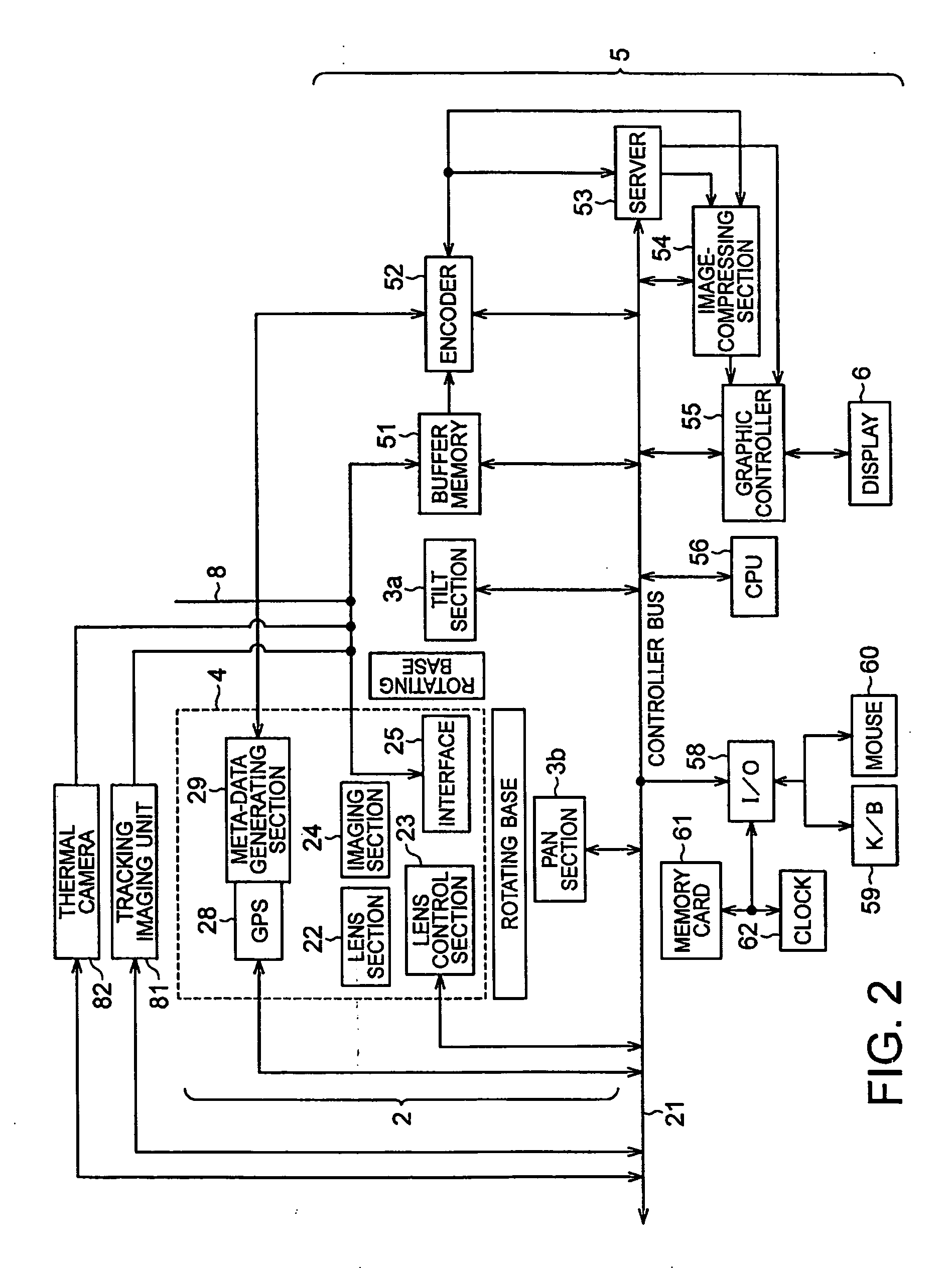
[0063] The preferred embodiment of the present invention will be described in detail, with reference to the accompanying drawings. As FIG. 1 shows, a monitor system 1 according to this invention comprises a camera unit 2, a tracking imaging unit 81, a thermal camera 82, a monitoring apparatus 5, a display 6, a terminal device 9, a terminal display 10, and a network 8. The camera unit 2 photographs an object, generating an image signal. The monitoring apparatus 5 receives an image signal from at least the camera unit 2. The display 6 is connected to the monitoring apparatus 5. The terminal device 9 is operated by users to execute application programs. The terminal display 10 is connected to the terminal device 9. The network 8 achieves interactive communication between the camera unit 2, monitoring apparatus 5 and terminal device 9.

[0064] The camera unit 2 incorporated in the monitor system 1 comprises a pan-tilter section 3 and a camera section 4 that are formed integral with each ...


PUM


Abstract

The present invention provides an imaging apparatus that monitors a broad area, day and night, to watch a specific object, such as a man, in connection with the background. The imaging apparatus includes a camera unit, a panorama-image generating section generating a panorama image of the entire area by combining a plurality of unit images obtained by the camera unit, a panorama-image storage/management section storing and managing the panorama image generated by the panorama-image generating section, a thermal camera photographing an object that has a temperature falling within a preset temperature range as a thermal image, a direction controller sequentially shifting the photographing direction of the thermal camera within the area being photographed, a thermal-image generating section combining a plurality of thermal images provided by the thermal camera, thereby to generate a panorama thermal image of the entire area, an image-synthesizing section synthesizing the panorama image generated by the panorama-image generating section, with the panorama thermal image generated by the thermal-image generating section, a display displaying the synthesized image generated by the image-synthesizing section.

Description

CROSS REFERENCES TO RELATED APPLICATIONS [0001] The present invention contains subject matter related to Japanese Patent Application JP 2004-188526 filed in the Japanese Patent Office on Jun. 25, 2004, the entire contents of which are incorporated herein by reference. BACKGROUND OF THE INVENTION [0002] 1. Field of the Invention [0003] The present invention relates to an imaging apparatus, method and program, for monitoring events occurring in a broad area, from a panorama image obtained by photographing the area while sequentially changing the photographing direction. The invention also relates to a recording medium and an imaging system. [0004] 2. Description of the Related Art [0005] In any electronic still camera hitherto used widely, the solid-state imaging element such as a CCD converts the light coming from an object through the lenses to an image signal. The image signal is recorded in a recording medium. The image signal can be reproduced from the recording medium. Most elec...

Claims


Application Information

Patent Timeline
IPC IPC(8): G06T7/00H04N5/262H04N5/33H04N7/18
CPCG06T7/0024G08B13/19608G08B13/19671H04N7/181G08B13/19689H04N5/23238H04N5/33G08B13/19682Y10S250/01G06T7/30H04N23/698
Inventor HASEGAWA, HIROYUKIKUREBAYASHI, MASAAKIMASE, MIKIKO
Owner SONY CORP
Why Eureka
Try Eureka