Modular transport system for coverings for architectural openings

a transport system and module technology, applied in the direction of door/window protective devices, building components, constructions, etc., can solve the problems of reducing the gap between the kicker and the spool, not being able to maintain constant force of the coiled spring motor used by the bixler, and wasting a lot of tim

Inactive Publication Date: 2006-01-05
HUNTER DOUGLAS INC
View PDF86 Cites 32 Cited by
  • Summary
  • Abstract
  • Description
  • Claims
  • Application Information

AI Technical Summary

Benefits of technology

[0014] The primary objective of the present invention is to provide a modular blind transport system which overcomes the shortcomings of prior blind transport systems. Rather than having to design a completely new system for each size and weight of blind, the designs of the present invention provide a system comprised of individual modules which are readily interconnected to satisfy the requirements of a multitude of different blind systems, it also includes the individual modules which make the overall system possible.
[0015] Accordingly, modularity is an important feature of the present invention. The individual modules in the present invention are contained in housings which make each element an independent and self contained module. Each module is easily and readily installed, mounted, replaced, removed, and interconnected within the blind transport system with an absolute minimum of time and expense. Each housing provides the mounting mechanism for its module onto the blind transport system, and removal of the housing also removes all the individual components which make up the module, leaving the balance of the blind transport system essentially unaffected except perhaps for the need to use a longer or shorter connecting rod.
[0017] The present invention overcomes the problem of the high friction and the interference fit between the wind-up spool and the kicker which acts as a shoulder to displace the coils of the lift cord such that there is no over-wrap. This is accomplished by moving the location of the kicker such that it no longer is immediately below the wind-up spool but rather is located beside the wind-up spool. Thus, any vertical displacement of the wind-up spool due to the weight of the blind will not adversely affect the clearance between the spool and the kicker.
[0025] By properly sizing and designing the individual modules, they can be made to work together interchangeably, permitting the development of a wide range of systems with a minimum number of different parts. For instance, a window covering may call for a certain size lightweight plastic blind including one coaxial coil spring motor, one transmission, and two lift stations. The same type of window covering but out of a much heavier wooden blind and for a much wider window may require two or more of the same coaxial coil springs motors connected in series, a similar transmission but with a different range, and several lift stations.

Problems solved by technology

However, the coiled spring motor used by Bixler is not a constant force motor.
Typically they displace the wind-up spool axially as the lift cord is wound up, requiring a complicated mechanism, or they have problems with over wrapping and tangling of the cord.
The weight of the blind pulls the spool downwardly, causing it to sag, and this can cause the gap between the kicker and the spool to be reduced to the point that there is interference between the spool and the kicker, creating friction.
All the different elements must be carefully mounted and placed so they will co-operate with each other and this is done at the expense of much time.
Furthermore, changing even one single characteristic of the blind (such as going from lightweight vinyl to heavy wooden blinds, or simply increasing the width or the length of the window covering) necessitates going through the entire time consuming process of customizing the entire blind transport system.
The nature of this process makes it expensive to truly customize a system in order to optimize its performance.

Method used


Image

  • Modular transport system for coverings for architectural openings
  • Modular transport system for coverings for architectural openings
  • Modular transport system for coverings for architectural openings

Examples


first embodiment

[0370] Typically a 3:1 transmission ratio is enough to handle the load of the lighter weight blinds (smaller blinds or blinds made out of plastic or fabric). However, for higher loads, such as those encountered when handling larger blinds or blinds made out of wood, a higher transmission ratio in the 5:1 range or higher may be required. The 3:1 transmission ratio can be achieved by having a smooth, unthreaded cylinder 402 (with no taper) (As shown in FIG. 65) in connection with a uniformly tapered threaded cone 412 which has a uniform pitch to the threads for its entire length, as was described with respect to the transmission 30. The result is a desirable, very linear power curve. In the 5:1 transmission, however, in order to keep the shafts 402, 412 short and stubby instead of long and slender, both the drive shaft and the driven shaft are tapered (as shown in FIG. 66). This brings in another complication—proper tracking of the cord 454 as described below.

[0371] In order for the t...

second embodiment

[0476]FIGS. 138-140 show the tilt only module 60A, in which the ladder pulley 62A has a non-cylindrical-profile hollow shaft 63A. In this case, the lift rod 26 not only goes through the hollow shaft 63A but also engages it, such that when the lift rod 26 rotates, it will cause the ladder pulley 62A to rotate as well. In this instance, the tilt cables 18 are not be secured to the ladder pulley 62A, but instead they are draped over the pulley as was discussed for the simultaneous lift / tilt module 500B (See FIG. 127). Now, as the lift rod 26 rotates, the ladder pulley 62A also rotates, pulling one tilt cable 18 up while the tilt cable 18 on the other side of the slats 14 is pushed down so as to close (or open) the slats 14. This action will continue until the lift rod 26 stops, or until the slats 14 reach a fully closed position. At that point, the resistance to continued rotation from the slats 14 will exceed the frictional resistance between the draped tilt cables 18 and the surface ...

third embodiment

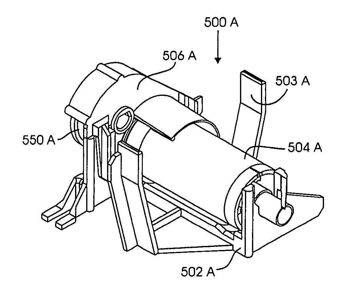
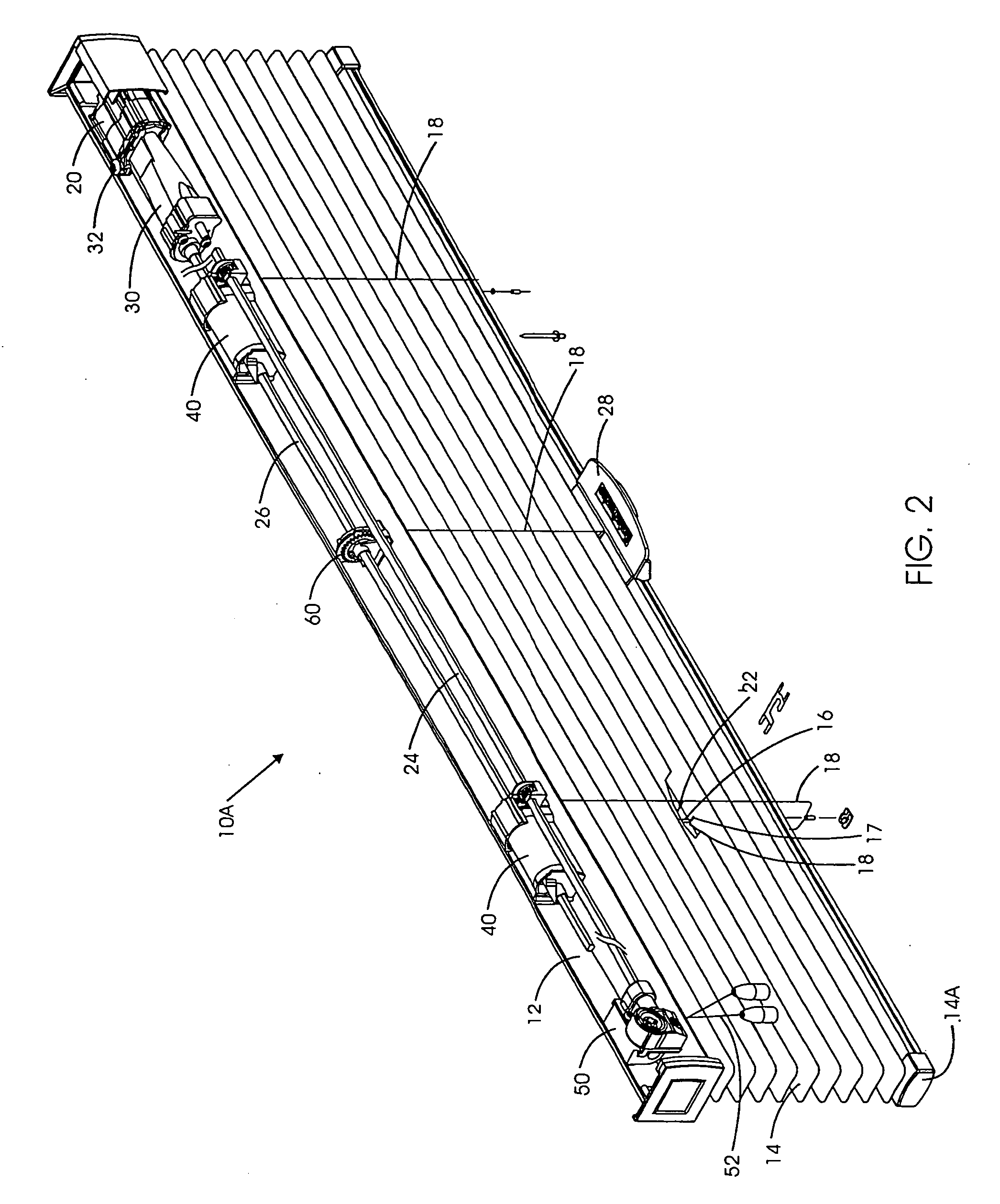
[0549] In FIG. 3, this invention, a standard rout product uses a simultaneous lift / tilt module 500B to eliminate the need for the cord tilter module 50 of FIG. 1. As the bottom rail 14A is raised, the lift cords 16 wind onto the lift spools 504B of the lift modules 500B, as has already previously been described. As each lift spool 504B rotates, the frictional resistance between the inside diameter of the shaft 587B of the ladder pulley 583B, and the outside diameter of the stub shaft 536B of the lift spool 504B, as well as the frictional resistance between the front end 526B of the spool 504B and the side of the ladder pulley 583B, will also cause the ladder pulley 583B to rotate, which will also cause the tilt cables 18 of the ladder tape 22 to move, raising one tilt cable 18 while lowering the other tilt cable 18. This action will continue until the bottom rail 14A motion is stopped, or until the slats 14 are fully closed in one direction or the other. Once the slats 14 are fully ...


PUM


Abstract

A modular blind transport system for a window blind application. The complete system may be assembled form a relatively small number of individual modules to obtain working systems for a very wide range of applications, including especially a category of counterbalanced blinds wherein a relatively small external input force may be used to raise or lower the blind, and / or to open or close the blind.

Description

BACKGROUND OF THE INVENTION [0001] This application takes priority from the Provisional U.S. Patent Application “Counter Balanced Transport for Blinds” filed on Mar. 23, 1999, Ser. No. 60 / 125,776, which is hereby incorporated by reference. The present invention relates to a modular transport system for opening and closing Venetian blinds, pleated shades, and other blinds and shades. While the embodiments shown herein are of horizontal blinds, the transport system may also be used on vertical blinds. [0002] In order to proceed, it is necessary to explain the operation of a blind transport system and to define some of the terms used. Typically, a blind transport system will have a top head rail which both supports the blind and hides the mechanisms used to raise and lower or open and close the blind. The raising and lowering is done by a lift cord attached to the bottom rail (or bottom slat). Thus, when raising a blind, at first only the bottom rail is being raised and the amount of f...

Claims


Application Information

Patent Timeline
Patent Type & Authority Applications(United States)
IPC IPC(8): E06B9/30E06B9/262E06B9/322
CPCE06B9/262E06B9/30E06B2009/2627E06B9/322E06B2009/2625E06B9/32
Inventor ANDERSON, RICHARDCOLSON, WENDELL B.HAARER, STEVEN R.
Owner HUNTER DOUGLAS INC
Why Eureka
Try Eureka