Method of and system for sharp object detection using computed tomography images
Active Publication Date: 2006-01-05
ANLOGIC CORP (US)
View PDF40 Cites 44 Cited by
Summary
Abstract
Description
Claims
Application Information
AI Technical Summary
This helps you quickly interpret patents by identifying the three key elements:
Problems solved by technology
Method used
Benefits of technology
Benefits of technology
[0055] The disclosed sharp object detection method provides substantial improvement in automatic object identification, classification and/or discrimination in CT scanning systems. Particularly, the three features, namely, the flat area, the axial concavity ratio, and the pointness measurement, which are specific to sharp objects, such as k
Problems solved by technology
The requirement for such attentiveness can result in greater operator fatigue, and fatigue as well as any distractions can result in a suspected bag passing through the system undetected.
Accordingly, a great deal of effort has been made to design a better baggage scanner.
However,
Method used
Image
Click on the blue label to locate the original text in one second.
Reading with bidirectional positioning of images and text.
Examples
Example
DETAILED DESCRIPTION OF THE DRAWINGS
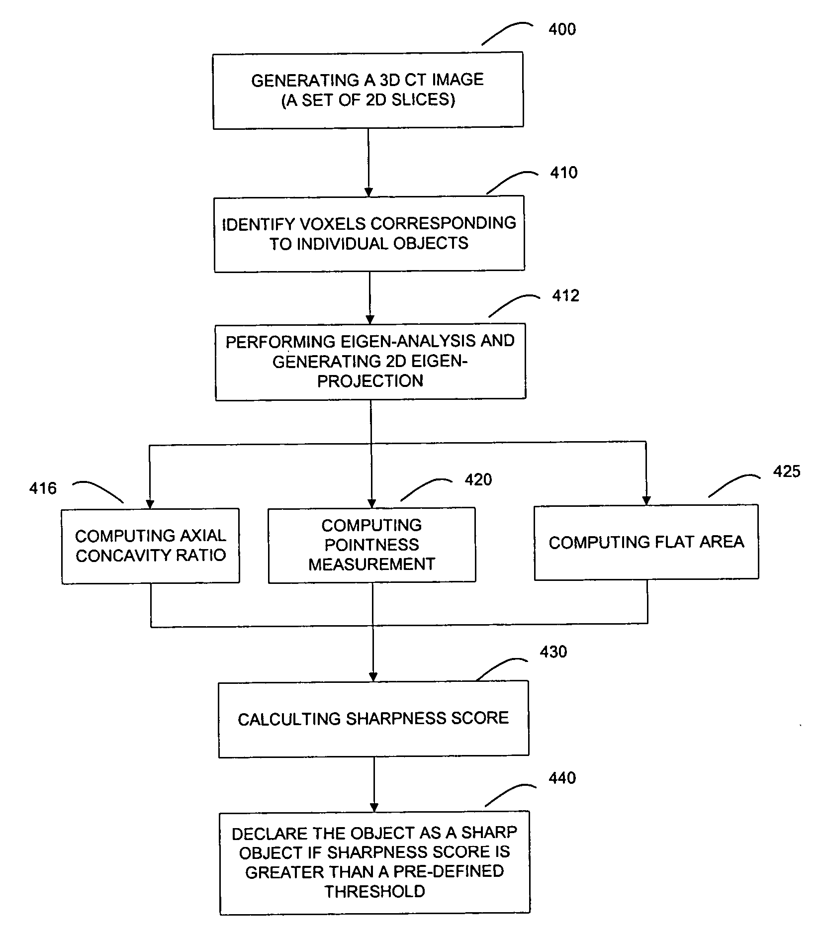
[0064] In accordance with the present disclosure, an algorithm for detecting sharp objects, such as knives, using CT images is provided. The algorithm uses features, which are specific to sharp objects in the CT images, in addition to measurements of mass and density for detection. These features are cascaded by using quadratic penalty functions to yield a sharpness score. The sharpness score is compared with a pre-defined threshold to detect the presence of a sharp object.
[0065]FIG. 4 contains a schematic flow diagram which illustrates the preferred embodiment of the logical flow of the process of detecting a sharp object using 3D CT images. At step 400, a 3D CT image with size of I×J×K voxels, denoted as A(i, j, k), i=0, . . . , I−1, j=0, . . . , J−1, k=0, . . . , K−1, is generated when a piece of luggage or baggage passes through the scanner, simlar to the one described herein in connection with FIGS. 1-3. Each voxel represents a spatial volu...
PUM
Abstract
A method of and a system for sharp object detection using computed tomography images are provided. The method comprises identifying voxels corresponding to individual objects; performing eigen-analysis and generating eigen-projection of an identified object; computing an axial concavity ratio of the identified object; computing a pointness measurement of the identified object; computing a flat area of the identified object; calculating a sharpness score of the identified object; and declaring the identified object as a threat if the sharpness score is greater than a pre-defined threshold.
Description
RELATED APPLICATIONS [0001] This patent application and / or patents are related to the following co-pending U.S. applications and / or issued U.S. patents, of the same assignee as the present application, the contents of which are incorporated herein in their entirety by reference: [0002]“Nutating Slice CT Image Reconstruction Apparatus and Method,” invented by Gregory L. Larson, et al., U.S. application Ser. No. 08 / 831,558, filed on Apr. 9, 1997, now U.S. Pat. No. 5,802,134, issued on Sep. 1, 1998; [0003]“Computed Tomography Scanner Drive System and Bearing,” invented by Andrew P. Tybinkowski, et al., U.S. application Ser. No. 08 / 948,930, filed on Oct. 10, 1997, now U.S. Pat. No. 5,982,844, issued on Nov. 9, 1999; [0004]“Air Calibration Scan for Computed Tomography Scanner with Obstructing Objects,” invented by David A. Schafer, et al., U.S. application Ser. No. 08 / 948,937, filed on Oct. 10, 1997, now U.S. Pat. No. 5,949,842, issued on Sep. 7, 1999; [0005]“Computed Tomography Scanning...
Claims
Application Information
Patent Timeline
Application Date:The date an application was filed.
Publication Date:The date a patent or application was officially published.
First Publication Date:The earliest publication date of a patent with the same application number.
Issue Date:Publication date of the patent grant document.
PCT Entry Date:The Entry date of PCT National Phase.
Estimated Expiry Date:The statutory expiry date of a patent right according to the Patent Law, and it is the longest term of protection that the patent right can achieve without the termination of the patent right due to other reasons(Term extension factor has been taken into account ).
Invalid Date:Actual expiry date is based on effective date or publication date of legal transaction data of invalid patent.
IPC IPC(8): G06K9/00
CPCG06T7/0004G06T2207/30112G06T2207/10081
InventorLARSON, GREGORY L.SIMANOVSKY, SERGEYYING, ZHENGRONGCRAWFORD, CARL R.

