System and method for using filtering and pixel correlation to increase sensitivity in image sensors

a technology of image sensor and filtering, applied in the field of solid-state imaging sensors, can solve the problems of missing, ignoring, or discarding imagery, and unable to detect, suppress false positives, and improve the sensitivity and false alarm rate. , the effect of improving the detection efficiency of targets

Active Publication Date: 2016-03-22
CYAN SYST
View PDF10 Cites 23 Cited by
  • Summary
  • Abstract
  • Description
  • Claims
  • Application Information

AI Technical Summary

Benefits of technology

[0023]According to one aspect of the present invention, oversampling of the minimum blur of an imaging system's optics overcomes the limitations posed by undersampling the image, as will be described in detail herein. Aspects of the invention include methods to oversample the limiting blur of imaging sensors. More particularly, the oversampled imagery from a small pixel array is processed in a way that improves the detectivity of targets, by correlating local pixels in the oversampled image, and suppresses false positives in the same oversampled image, thus resulting in the ability to improve the sensitivity and the false alarm rate in real imagery.

Problems solved by technology

There is uncertainty in the arrival of photons in time, and uncertainty as to where the photon will land on the focal plane array.
Because most sensors provide a pixel size that is within a factor of the size of the blur, which is limited by the physical sensor aperture and system optics, often times there are aliasing and artifacts associated with such imagers.
Past techniques have involved missing, ignoring, or discarding imagery due to lower resolution, higher noise, or challenges with transmitting, storing, and processing high data rate imagery.
Yet other techniques have controllable resolution, but do not posses the means to first detect the entire scene at a high resolution and to then tell the imaging system to provide a lower resolution image to save on bandwidth by not transmitting unwanted imagery data.
The problem with these variable resolution approaches is that if there is a new target that appears within a region of lower resolution, the target may not be detected unless another system tells the lower resolution sensor to increase its resolution or, if there is apriori information about the expected appearance of an object or target.
Pixel size has been limited by the ability to create the necessary interconnect pads and deposit the metal onto the small pads.
This in turn limited the ability to have smaller pixels for, for example, infrared (IR) imagers.
Furthermore, since the blur size of IR sensors was typically greater than 15 um, some researchers indicated that it was unnecessary to provide for pixels that were much smaller than the pixels of IR imagers.
Another limitation of the Super Resolution techniques for reconstruction is that because they require several frames of data, by definition they have latency in the processing and identification of potential objects or targets.
In some cases, the latency results in the inability to track and identify fast moving objects in larger imagery formats.
Yet another limitation of the Superresolution reconstruction techniques is their computational complexity, so that larger computers with near real time capability or with near real time capability are required in order to construct and compute the Super Resolution image.
In addition, continuously providing Super Resolution requires that each frame needs to be processed, thus increasing the computational complexity to such a degree that such processing becomes more difficult as the format of the imager increases, and also when the frame rate increases.
In the past the pixel size was limited by the ability to create the necessary interconnect pads and deposit the metal onto the small pads.
This in turn limited the ability to have smaller pixels for IR imagers.
Limitations to these Superresolution Reconstruction techniques are that they can require several image frames to create a higher effective resolution image out of several low resolution frames and, moreover, impose challenging computational complexity and costs to the system.
Another limitation of current imagers is the detection of dim targets in clutter without false alarms.
Another disadvantage of current undersampled imagers is that, when there is platform motion, turbulence, dust / haze and / or other movements, the incident photons are further distributed to other pixels in a manner that will degrade the blur size of an ideal Point Spread Function (PSF).
This causes image pixel smears and integrated signal reduction, making it more difficult to detect objects under even limited motion.
For target detection sensors, a limitation in sensitivity arises due to the random arrival of photons, which create photon shot noise and limit the Noise Equivalent detectable Power (NEP).
Conversely, if there is an exceedance of the threshold in one superpixel, but not sufficient exceedances in the neighboring pixels, this indicates an uncorrelated exceedance, which indicates noise noise.
Brown Out occurs when severe windage by helicopters or air turbulence causes severe refractory inducing wind pressure changes and dust disturbance.

Method used


Image

  • System and method for using filtering and pixel correlation to increase sensitivity in image sensors
  • System and method for using filtering and pixel correlation to increase sensitivity in image sensors
  • System and method for using filtering and pixel correlation to increase sensitivity in image sensors

Examples


Embodiment Construction

[0097]The embodiments and variations of the invention described herein, are presented by way of example only and are not limiting as to the scope of the invention. Unless otherwise specifically stated, individual aspects and components of the invention may be omitted or modified, or may have substituted therefore known equivalents, or as yet unknown substitutes such as may be developed in the future or such as may be found to be acceptable substitutes in the future. The invention may also be modified for a variety of applications while remaining within the spirit and scope of the claimed invention, since the current invention has multiple applications within several fields for a wide variety of imaging and surveillance systems.

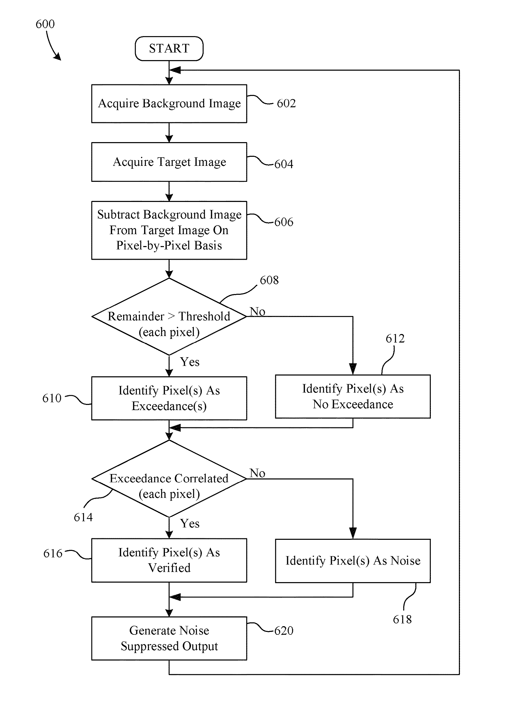
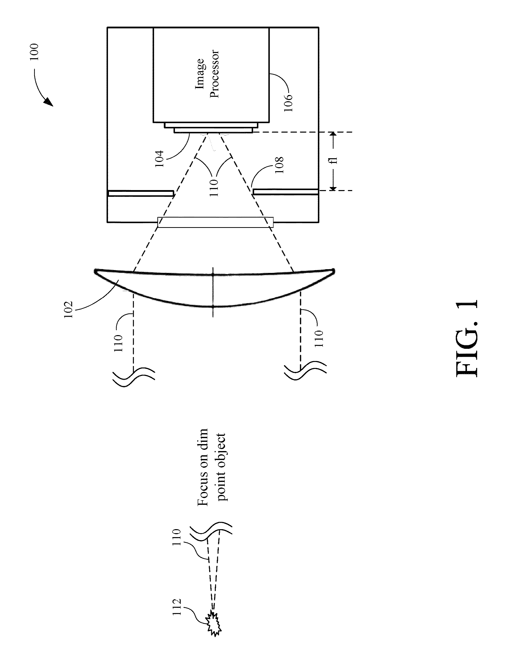
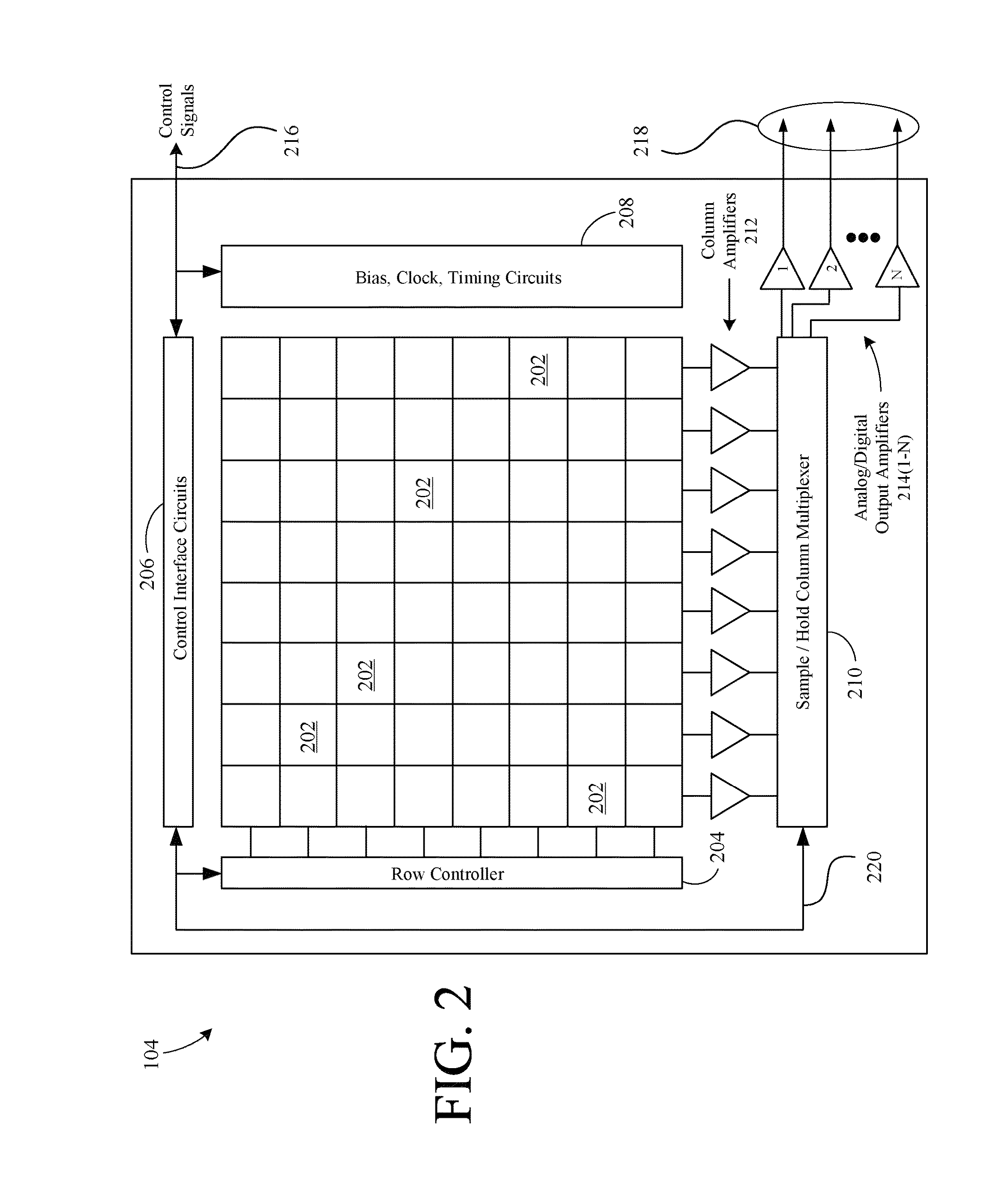
[0098]An example embodiment of the present invention includes a highly pixilated sensor array. The pixilation facilitates a plurality of temporal and spatial sampling and filtering combinations or modes. Aspects of the invention provide improved noise characte...


PUM


Abstract

An over sampled image sensor in which the pixel size is small enough to provide spatial oversampling of the minimum blur size of the sensor optics is disclosed. Image processing to detect targets below the typical limit of 6× the temporal noise floor is also disclosed. The apparatus is useful in detecting dimmer targets and targets at a longer range from the sensors. The inventions exploits signal processing, which allows spatial temporal filtering of the superpixel image in such manner that the Noise Equivalent Power is reduced by a means of Superpixel Filtering and Pooling, which increases the sensitivity far beyond a non-oversampled imager. Overall visual acuity is improved due to the ability to detect dimmer targets, provide better resolution of low intensity targets, and improvements in false alarm rejection.

Description

RELATED APPLICATIONS[0001]This application claims the benefit of U.S. Provisional Patent Application No. 61 / 553,017 entitled System and Method for Using Pixel Correlation in Image Sensors, filed Oct. 28, 2011 by the same inventor, which is incorporated herein by reference in its entirety.[0002]This application is a continuation-in-part of prior co-pending U.S. patent application Ser. No. 12 / 101,139, entitled Image Detection With Automated Sensing Of An Object Or Characteristic Of That Object, filed on Apr. 10, 2008 by the same inventor, which is incorporated herein by reference in its entirety.GOVERNMENT INTEREST[0003]This invention was made with government support awarded by the Defense Advanced Research Project Agency / Army Contracting Command, contract W31P4Q-10-C-0040. The Government has certain rights in the invention.BACKGROUND[0004]1. Field of the Invention[0005]The present invention is related to solid state imaging sensors. More particularly, the present invention is related...

Claims


Application Information

Patent Timeline
Patent Type & Authority Patents(United States)
IPC IPC(8): G06K9/00H04N5/33
CPCH04N5/33H01L27/14609H01L27/14625H01L27/14634H01L27/14636H01L27/14685H01L27/1469H04N25/60H04N25/616H04N25/75H04N25/534H04N25/771
Inventor CAULFIELD, JOHN, T.
Owner CYAN SYST
Why Eureka
Try Eureka