Combined liquefied gas and compressed gas re-fueling station and method of operating same

a liquefied gas and compressed gas technology, applied in the direction of positive displacement liquid engine, container discharging method, packaged goods type, etc., can solve the problems of increasing the weight of the storage tank, requiring additional equipment, and adding extra heat into the storage tank, so as to reduce the cost of capital and maintenance costs

Inactive Publication Date: 2006-01-12
WESTPORT POWER
View PDF33 Cites 27 Cited by
  • Summary
  • Abstract
  • Description
  • Claims
  • Application Information

AI Technical Summary

Benefits of technology

[0048] In all methods, the hydraulic pump system preferably comprises a single hydraulic pump, for reduced capital costs and lower maintenance costs. However, a plurality of hydraulic pumps may also be employed without departing from the spirit of this invention. For example, a re-fueling station may employ a stand-by hydraulic pump, or a tandem arrangement, depending upon the needs of the re-fueling station.

Problems solved by technology

CNG can be stored at higher pressures, but this adds to the weight of the storage tanks because they need to be designed and certified for such higher pressures.
However, such pressure transfer systems result in extra heat being introduced into the storage tank, and may require additional equipment to prevent over-pressurization of the LNG storage tank.
Another disadvantage with a pressure transfer system is that fuel delivery can be delayed since it takes time to build pressure within the storage tank.
Even though conventional CNG compressors operate at relatively high speeds, flow rates are typically relatively low.
The divergent operating conditions between re-fueling stations for LNG (low pressure with high mass flow rate) and CNG (high pressure with low mass flow rate) have presented a challenge for designing a simple re-fueling station capable of delivering both LNG and CNG, especially when it is desirable to have a system with only one fuel pump or compressor for quickly dispensing either LNG or CNG.
However, as already noted, there are disadvantages associated with a pressure transfer system, such as more frequent venting from the LNG storage tank when pressure within the storage tank exceeds a predetermined maximum pressure.
Venting from the LNG storage tank results in wasted natural gas.
However, such arrangements add to the complexity of the system in addition to increased capital and operational costs.

Method used


Image

  • Combined liquefied gas and compressed gas re-fueling station and method of operating same
  • Combined liquefied gas and compressed gas re-fueling station and method of operating same
  • Combined liquefied gas and compressed gas re-fueling station and method of operating same

Examples


Embodiment Construction

(s)

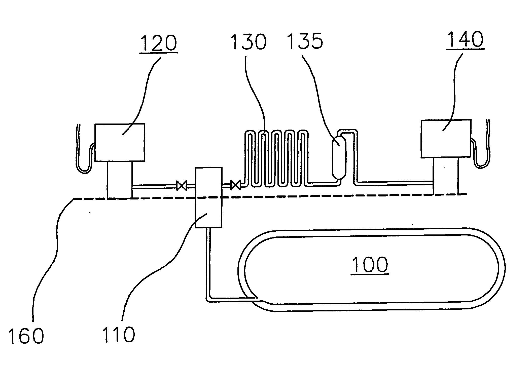
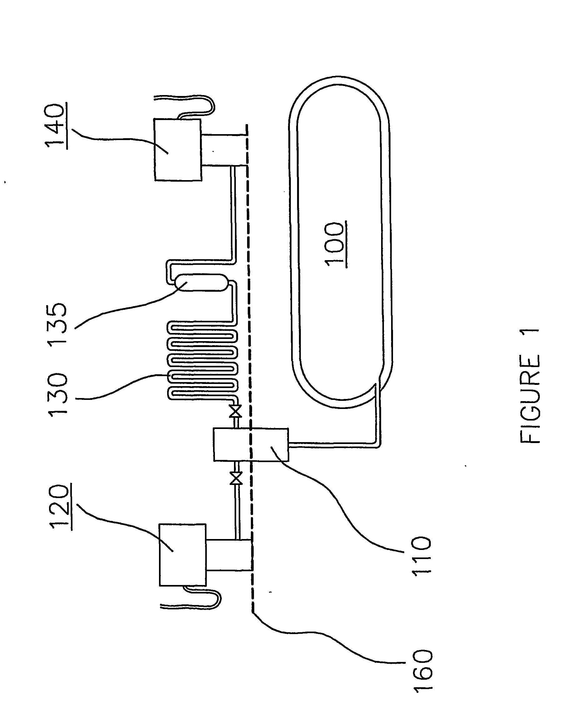
[0055] Referring to FIG. 1, a combined liquefied gas and compressed gas re-fueling station comprises LNG storage tank 100, fuel pump unit 110, LNG dispenser 120, heat exchanger 130 and CNG dispenser 140. Odorizer 135 is typically required to add an odor to CNG so as to comply with safety regulations. Dashed line 160 indicates ground level.

[0056] In a preferred embodiment, LNG storage tank 100 is buried underground. As noted above, since LNG is stored at cryogenic temperatures (typically less than −175° F. (−115° C.) for LNG), an advantage of burying LNG storage tank 100 compared to a tank situated above ground, is that there is much less temperature variation around underground LNG storage tank 100. Another advantage is that an underground storage tank conserves more space above ground for improved accessibility of vehicles to the dispensers. Building codes also typically require less distance between an underground storage tank and an adjacent property, compared to an above-gro...


PUM

PropertyMeasurementUnit
pressuresaaaaaaaaaa
pressuresaaaaaaaaaa
temperaturesaaaaaaaaaa

Abstract

A re-fueling station is provided for selectively dispensing fuel in the form of liquefied gas or compressed gas. The re-fueling station comprises a storage tank within which liquefied gas may be stored; a dispensing system comprising: (a) a first dispenser for dispensing compressed gas; (b) a second dispenser for dispensing liquefied gas; (c) a heat exchanger operable to transfer heat to the fuel; (d) a flow diverter operable to receive fuel through an inlet and selectively direct fuel through one of a first outlet or a second outlet; (e) conduits through which fuel may flow from the first outlet to the heat exchanger and then to the first dispenser, or from the second outlet to the second dispenser; and, (f) a positive displacement fuel pump operable to draw fuel from the storage tank and discharge fuel to the inlet of the flow diverter. A method of operating the re-fueling station comprises operating the fuel pump in a low speed mode when fuel is directed to said first dispenser to supply compressed gas and operating the fuel pump in a high speed mode when fuel is directed to the second dispenser to supply liquefied gas.

Description

FIELD OF THE INVENTION [0001] This invention relates to a re-fueling station for vehicles. More particularly, the invention relates to a re-fueling station that can supply either liquefied gas or compressed gas, as required by the vehicle, and a method of operating such a station. While not wishing to be limited to any particular fuel gas, natural gas shall be used as a convenient example, and references to the fuel hereafter will be to liquefied natural gas (LNG) and compressed natural gas (CNG). Those skilled in the art will understand that a different liquefied fuel gas such as hydrogen may be substituted for natural gas without deviating from the spirit of the disclosed invention. BACKGROUND OF THE INVENTION [0002] Natural gas has been used as a fuel for piston engine driven vehicles for over fifty years. The desire to improve efficiency and reduce pollution is causing continual change and improvements in the available technology. Some companies are also researching the use of o...

Claims


Application Information

Patent Timeline
Patent Type & Authority Applications(United States)
IPC IPC(8): B65B1/04F04B5/02F04B15/08F17C5/02F17C5/00F17C5/06F17C13/02
CPCF04B5/02F04B15/08F17C5/007F17C2265/065F17C2270/0139F17C2265/027F17C2223/0123F17C2223/0161F17C2223/033F17C2223/036F17C2227/0302F17C2221/033
Inventor GRAM, ANKERURSAN, MIHAI
Owner WESTPORT POWER
Why Eureka
Try Eureka