Liquid crystal display device and method of driving liquid crystal display device

a liquid crystal display and display device technology, applied in the direction of instruments, computing, electric digital data processing, etc., can solve the problems of slow response speed, inferior image quality to that of cathode ray tubes, and lingering, and achieve the effect of minimalism brightness

Inactive Publication Date: 2006-01-12
TOSHIBA MATSUSHITA DISPLAY TECH
View PDF18 Cites 34 Cited by
  • Summary
  • Abstract
  • Description
  • Claims
  • Application Information

AI Technical Summary

Benefits of technology

[0049] The present invention provides a liquid crystal display device and a method of driving the liquid crystal display device capable of realizing a black display with minimum brightness even if temperature increases.

Problems solved by technology

However, a TN (Twisted Nematic) aligned liquid crystal panel which is currently used in a wide range has a narrow view angle, a slow response speed and its image quality is inferior to that of a cathode ray tube, for example, when a moving image is displayed its image appears to linger.
However, as is also seen in a TN aligned liquid crystal display device, in the case of a liquid crystal display device using an OCB mode in particular, when the temperature increases, the voltage corresponding to the minimum brightness decreases, and therefore even when a black display is performed, the display may appear rather bright.
That is, in the case of the conventional liquid crystal display device using an OCB mode, when the temperature increases, even in the case of a black display, optical compensation cannot be attained and a black color is displayed brightly, which results in a problem of reducing contrast.
Furthermore, the conventional liquid crystal display device using an OCB mode has a problem that when the temperature changes, brightness displayed differs from the brightness to be actually displayed.

Method used


Image

  • Liquid crystal display device and method of driving liquid crystal display device
  • Liquid crystal display device and method of driving liquid crystal display device
  • Liquid crystal display device and method of driving liquid crystal display device

Examples


first embodiment

[0083] First, a first embodiment will be explained.

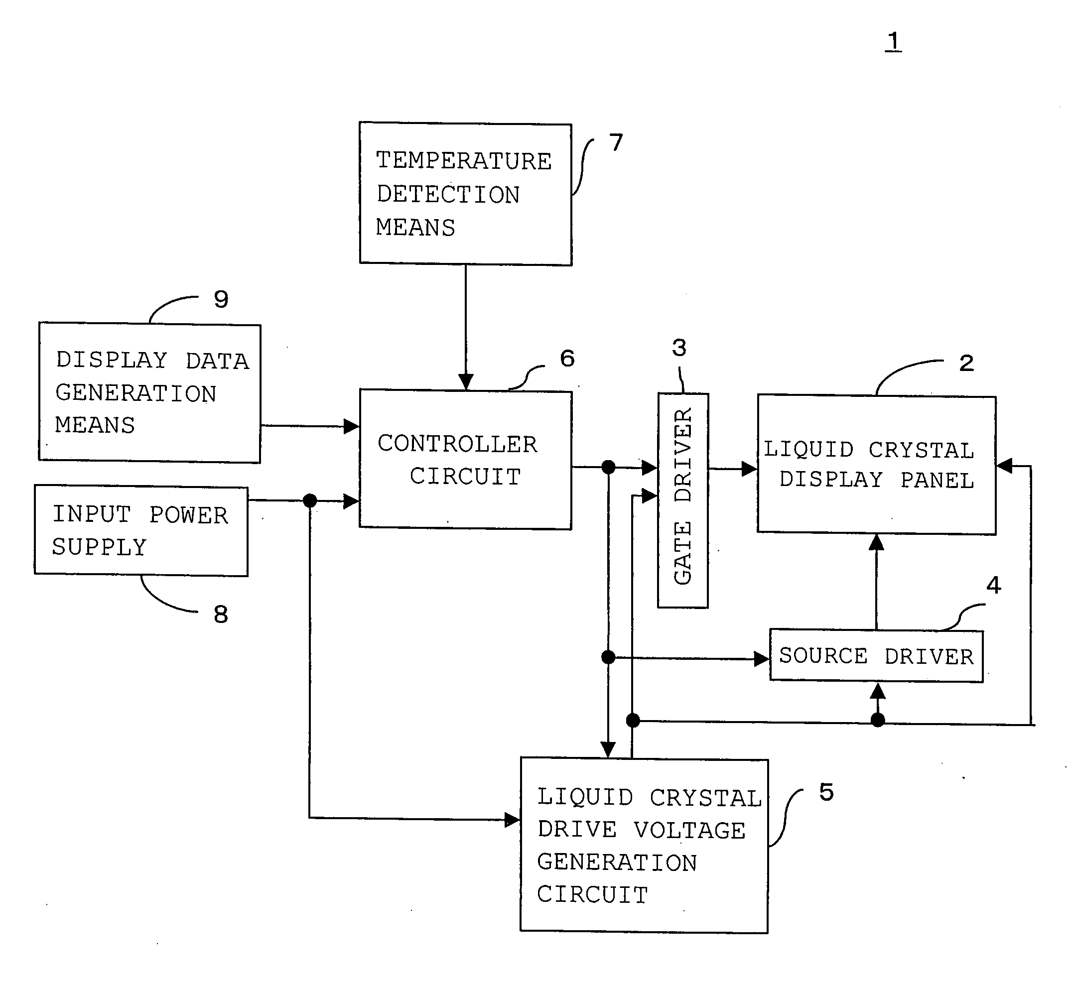
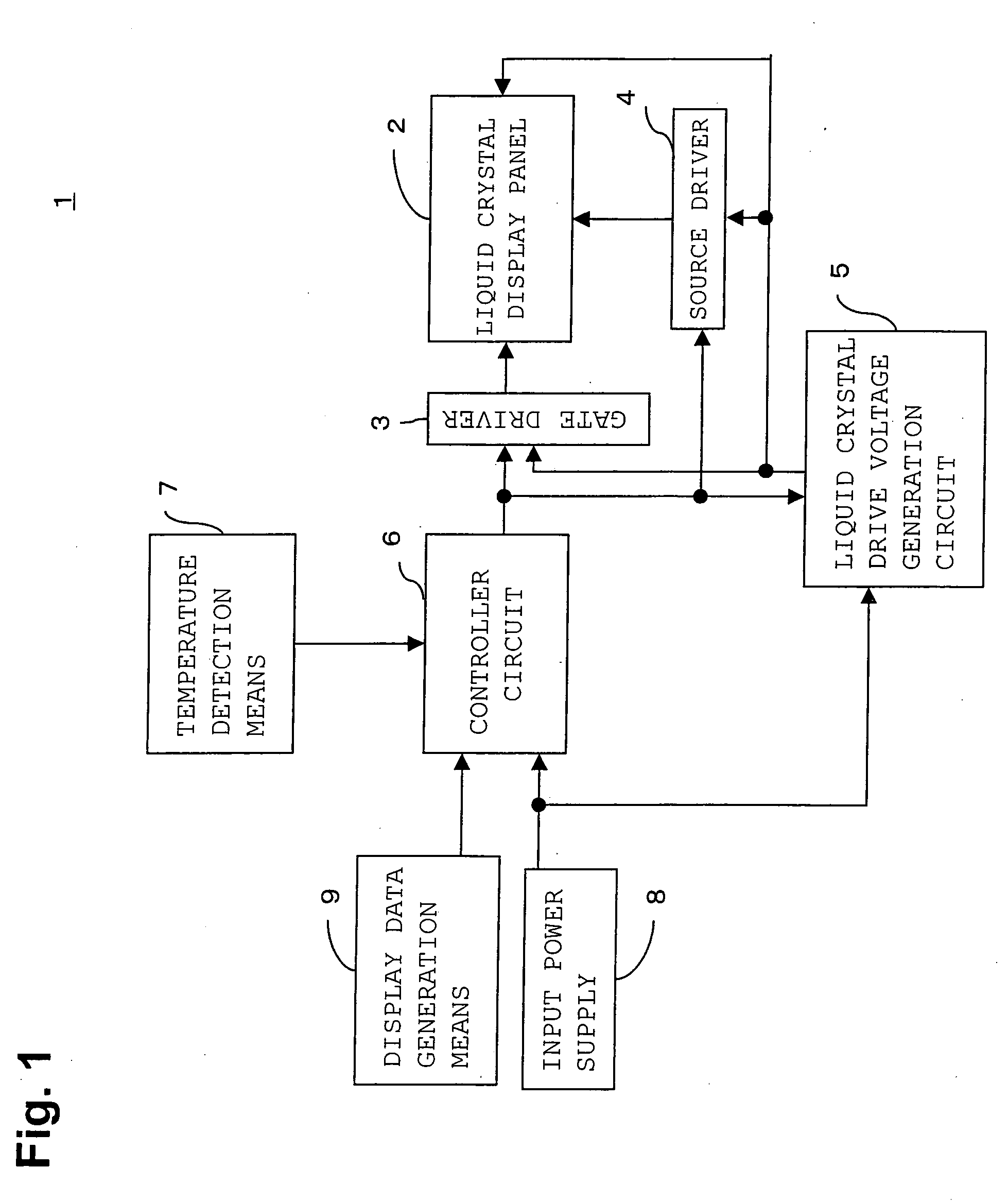
[0084]FIG. 1 shows a block diagram of a liquid crystal display device 1 of a first embodiment.

[0085] A liquid crystal display device 1 is a liquid crystal display device using OCB mode liquid crystal.

[0086] The liquid crystal display device 1 is constructed of a liquid crystal display panel 2, a gate driver 3, a source driver 4, a liquid crystal drive voltage generation circuit 5, a controller circuit 6, a temperature detection means 7, an input power supply 8 and a display data generation means 9.

[0087] The liquid crystal display panel 2 is a display panel having source signal lines and gate signal lines arranged in matrix form and liquid crystal elements provided at intersections between the source signal lines and gate signal lines and using OCB mode liquid crystal.

[0088] The gate driver 3 is a circuit that supplies a selection scanning signal for carrying out linear sequential scanning of each gate signal line of the liquid...

second embodiment

[0116] Next, a second embodiment will be explained.

[0117]FIG. 6 shows a block diagram of a liquid crystal display device 12 according to a second embodiment.

[0118] The liquid crystal display device 12 is a liquid crystal display device using OCB mode liquid crystal as in the case of the first embodiment.

[0119] The liquid crystal display device 12 is constructed of a liquid crystal display panel 2, a gate driver 3, a source driver 4, a liquid crystal drive voltage generation circuit 13, a controller circuit 14, temperature detection means 7 and an input power supply 8. As in the case of the first embodiment, the second embodiment is also provided with a display data generation circuit, which is not shown for simplicity.

[0120] The liquid crystal display device 12 according to the second embodiment differs from the liquid crystal display device 1 according to the first embodiment in the controller circuit and liquid crystal drive voltage generation circuit 13.

[0121] That is, the c...


PUM

PropertyMeasurementUnit
temperatureaaaaaaaaaa

Abstract

A liquid crystal display device includes a liquid crystal display panel having source signal lines and gate signal lines arranged in matrix form and liquid crystal display elements using OCB mode liquid crystal, the liquid crystal display elements being provided at intersections between the source signal lines and gate signal lines; a gate driver that supplies a gate signal to said gate signal lines; a source driver that supplies a voltage corresponding to gradation of display data to said source signal lines during a display period; temperature detection means of detecting temperature; and correcting means of correcting display data for generating the source signal to display data according to the detected temperature, wherein the source signal is generated based on the corrected display data.

Description

BACKGROUND OF THE INVENTION [0001] 1. Field of the Invention [0002] The present invention relates to a liquid crystal display device using an OCB mode liquid crystal and a method of driving the liquid crystal display device. [0003] 2. Prior Art of the Invention [0004] A liquid crystal display device is thin and light, and has been used in an increasingly wide range of application as a substitute for a conventional cathode ray tube in recent years. However, a TN (Twisted Nematic) aligned liquid crystal panel which is currently used in a wide range has a narrow view angle, a slow response speed and its image quality is inferior to that of a cathode ray tube, for example, when a moving image is displayed its image appears to linger. [0005] In contrast, a liquid crystal display device using an OCB (Optically Compensated Bend) mode featuring high-speed response and a broad view angle is available in recent years. This liquid crystal display device is designed to obtain a wide view angle ...

Claims


Application Information

Patent Timeline
Patent Type & Authority Applications(United States)
IPC IPC(8): G09G5/00G02F1/133G09G3/36
CPCG09G3/3651G09G3/3655G09G3/3696G09G2340/0428G09G2320/041G09G2320/066G09G2320/0276G09G3/36
Inventor KAWAGUCHI, SEIJI
Owner TOSHIBA MATSUSHITA DISPLAY TECH
Why Eureka
Try Eureka