Display device

a display device and display screen technology, applied in the field of display devices, can solve the problems of deteriorating work efficiency, unattractive cabinets, complex arrangements, etc., and achieve the effect of improving exterior design and standing alon

Inactive Publication Date: 2006-01-19
ORION ELECTRIC CO LTD
View PDF14 Cites 13 Cited by
  • Summary
  • Abstract
  • Description
  • Claims
  • Application Information

AI Technical Summary

Benefits of technology

[0007] The present invention aims at solving the problems of the prior art mentioned above, by providing a display device having the bracket to which the display unit is fixed covered by the back cabinet to improve the exterior design, capable of detaching the stand without removing the back cabinet, and capable of having the display portion stand alone stably when adjusting the liquid crystal panel.

Problems solved by technology

The arrangement disclosed in patent documents 1 through 4 having the bracket of the stand fixed either directly to the back cabinet or to the mounting cover of the liquid crystal panel disposed in the cabinet is not attractive from the view point of exterior design, since the bracket and the multiple fixing screws for fixing the bracket are directly visible to the exterior.
Therefore, according to patent document 5, an engagement unit with a spring-like structure is fixed inside the hollow portion to be engaged to a hole formed to the simplified stand to prevent the display portion from being easily detached from the base stand, which causes the arrangement to be complex with respect to the arrangements of patent documents 1 through 4 where the stand is fixed simply via fixing screws.
However, if the bracket or the fixing screws are covered by the back cabinet, when it is necessary to detach the display portion from the stand for example to hang the display on the wall, the back cabinet must first be removed before disengaging the fixing screws fixing the display portion to the stand, deteriorating work efficiency.
Moreover, various adjustment works such as color adjustment, color correction and image position adjustment of the liquid crystal panel are required in these types of display devices, but since the display portion cannot be supported without the stand, the adjustment work cannot be carried out stably without the stand.

Method used


Image

  • Display device
  • Display device
  • Display device

Examples


Embodiment Construction

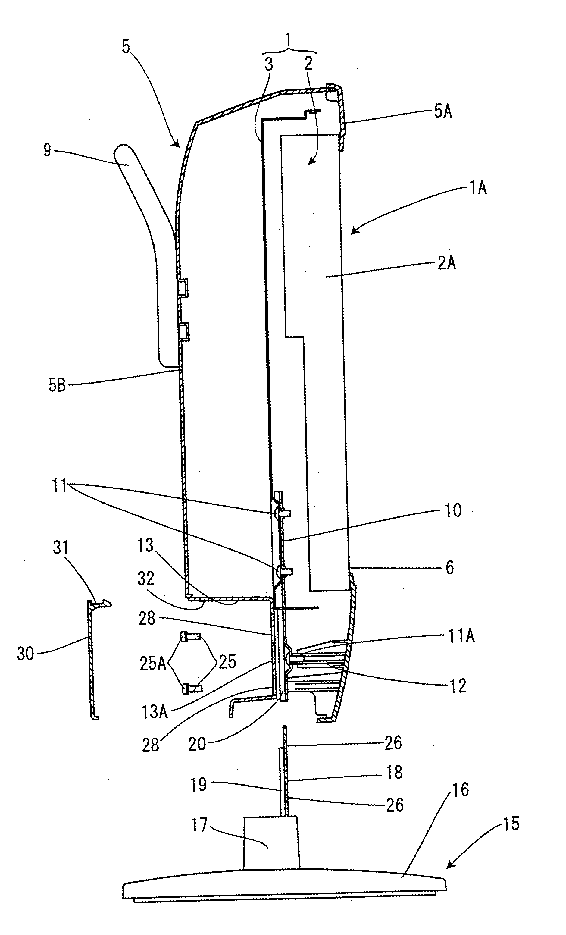
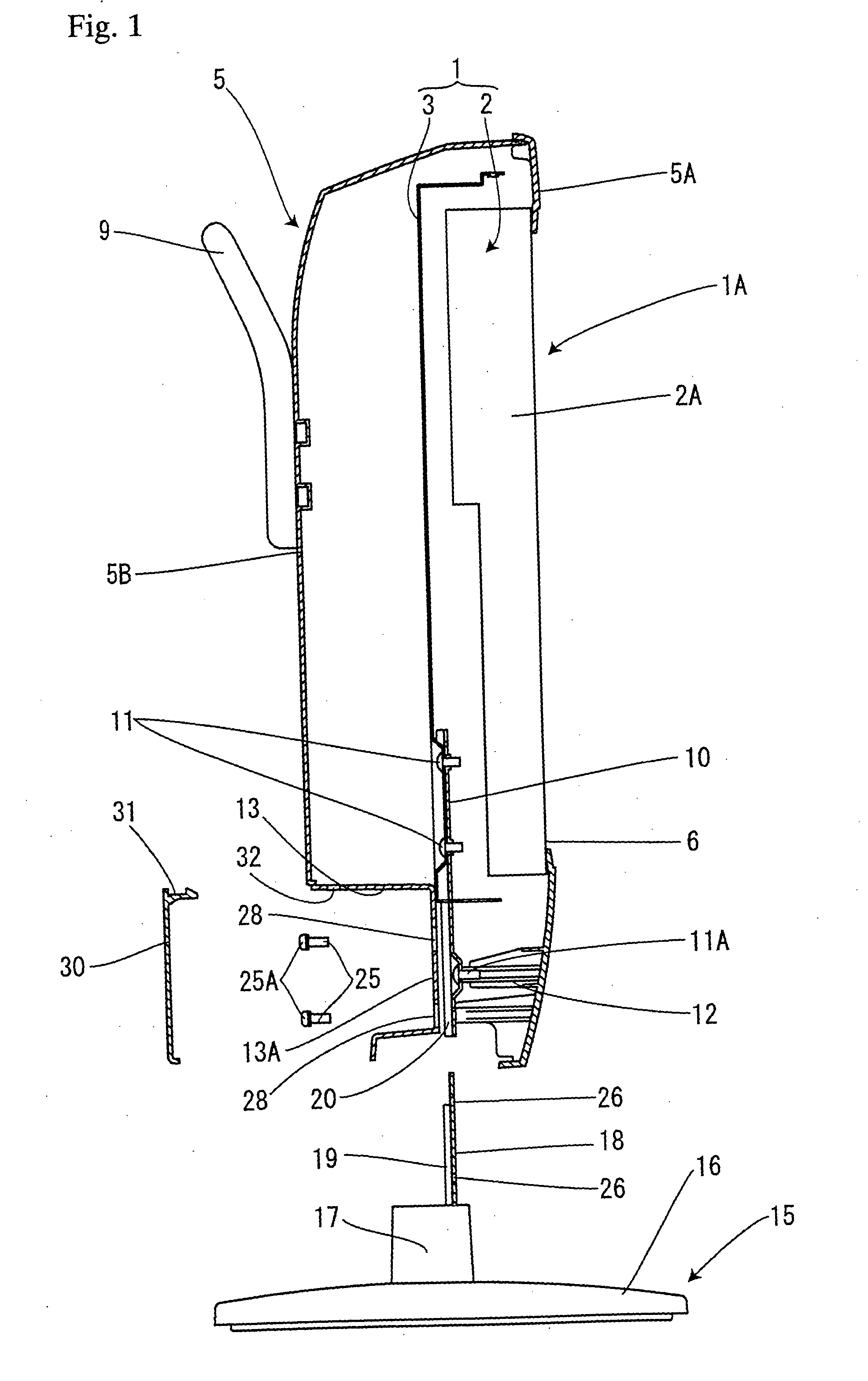
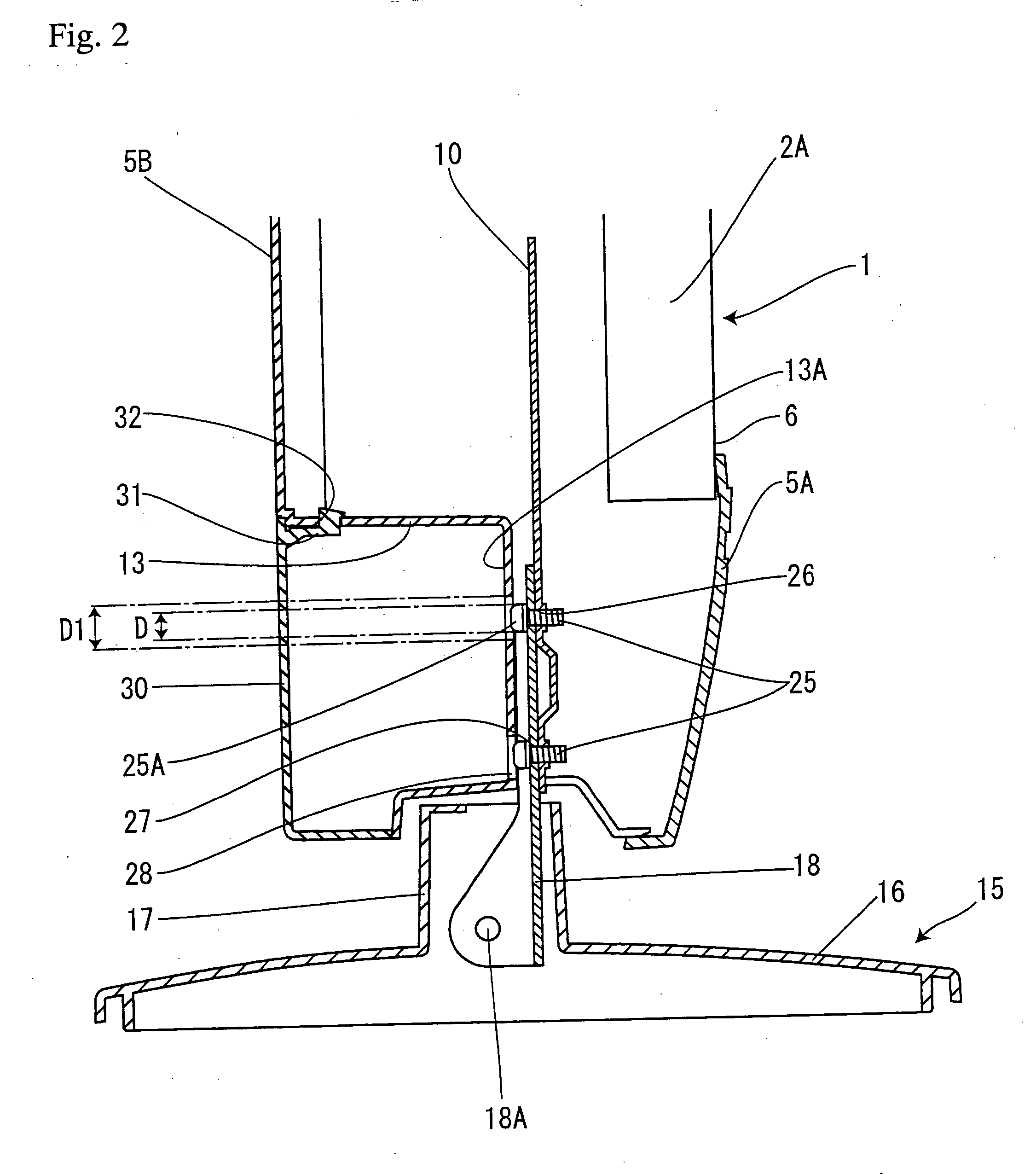
[0028] Now, the preferred embodiments for carrying out the present invention will be described with reference to the drawings. FIGS. 1 through 6 illustrate a preferred embodiment of the present invention, wherein reference number 1 denotes a display unit composed of a liquid crystal panel 2 and a metallic mounting cover 3 for fixing the liquid crystal panel 2 to a cabinet described in detail later. The liquid crystal panel 2 has a liquid crystal display device body and a metallic panel fixing frame 2A covering the outer circumference of the liquid crystal display device body from its rear face, wherein the panel fixing frame 2A is fixed to the mounting cover 3 via multiple screws (not shown). A cabinet 5 to which the liquid crystal panel 2 is assembled is separated into a front cabinet 5A and a back cabinet 5B, wherein the front cabinet 5A has a display window 6 for the liquid crystal panel 2, and the front cabinet 5A and the back cabinet 5B are fixed via screws 8 as illustrated in ...


PUM

PropertyMeasurementUnit
inner diameteraaaaaaaaaa
diameteraaaaaaaaaa
heightaaaaaaaaaa

Abstract

The invention provides a display device having an improved exterior appearance by covering a bracket including a display unit with a back cabinet, capable of having a stand attached thereto and removed therefrom without taking off the back cabinet. A display unit 1 is fixed inside a cabinet 5 composed of a front cabinet 5A and a back cabinet 5B. An opening 28 is formed to the back cabinet 5B having an inner diameter D1 greater than an outer diameter D of a head portion 25A of a fixing screw 25. Thus, the stand 15 can be disassembled from the display unit 1 without taking off the back cabinet 5B, by removing a disengaged fixing screw 25 through the opening 28 to the exterior.

Description

[0001] The present application is based on and claims priority of Japanese patent application No. 2004-210436 filed on Jul. 16, 2004, the entire contents of which are hereby incorporated by reference. BACKGROUND OF THE INVENTION [0002] 1. Field of the Invention [0003] The present invention relates to a display device, and more specifically, to a display device having a display unit with a liquid crystal panel and a detachable stand for supporting the display unit. [0004] 2. Description of the Related Art [0005] In recent years, thin flat panel display devices such as PDP and liquid crystal panels are widely used as display devices for personal computers and television receivers. Such display devices utilizing liquid crystal panels have a stand that supports the display portion when placed on the floor or the like. Various arrangements of the display device with a stand have been proposed. For example, Japanese Patent Application Laid-Open Publications No. 2001-332074, No. 2003-8252,...

Claims


Application Information

Patent Timeline
Patent Type & Authority Applications(United States)
IPC IPC(8): G04B37/14H04N5/64F16M11/00G02F1/1333G06F1/16G09F9/00
CPCF16M11/00F16M11/10G06F2200/1612F16M2200/08G06F1/1601F16M11/22
Inventor AKAGAWA, KOUJISHIMOSHITA, KENJI
Owner ORION ELECTRIC CO LTD
Why Eureka
Try Eureka