Method and apparatus for equalizing pressure between rollers in a printing press

a printing press and roller technology, applied in the field of printing presses, can solve the problems of image damage during transfer, increased wear rate of both itm blanket and pic photo surface, and image colors being washed out,

Active Publication Date: 2006-01-19
HEWLETT PACKARD INDIGO BV
View PDF1 Cites 45 Cited by
  • Summary
  • Abstract
  • Description
  • Claims
  • Application Information

AI Technical Summary

Problems solved by technology

If contact pressure between the PIC and ITM is too high, the image may be damaged during transfer, for example, by dot spreading or blurring of the image.
Too much pressure also usually results in an increased wear rate for both the ITM blanket and PIC photosurface.
On the other hand, if contact pressure between the ITM and PIC is too low, too little toner may be transferred from the PIC to the ITM, resulting in colors in the image being washed out.
However, visual inspection and manual pressure adjustment are subjective, generally tedious and wasteful of press operator time.

Method used


Image

  • Method and apparatus for equalizing pressure between rollers in a printing press
  • Method and apparatus for equalizing pressure between rollers in a printing press
  • Method and apparatus for equalizing pressure between rollers in a printing press

Examples


Embodiment Construction

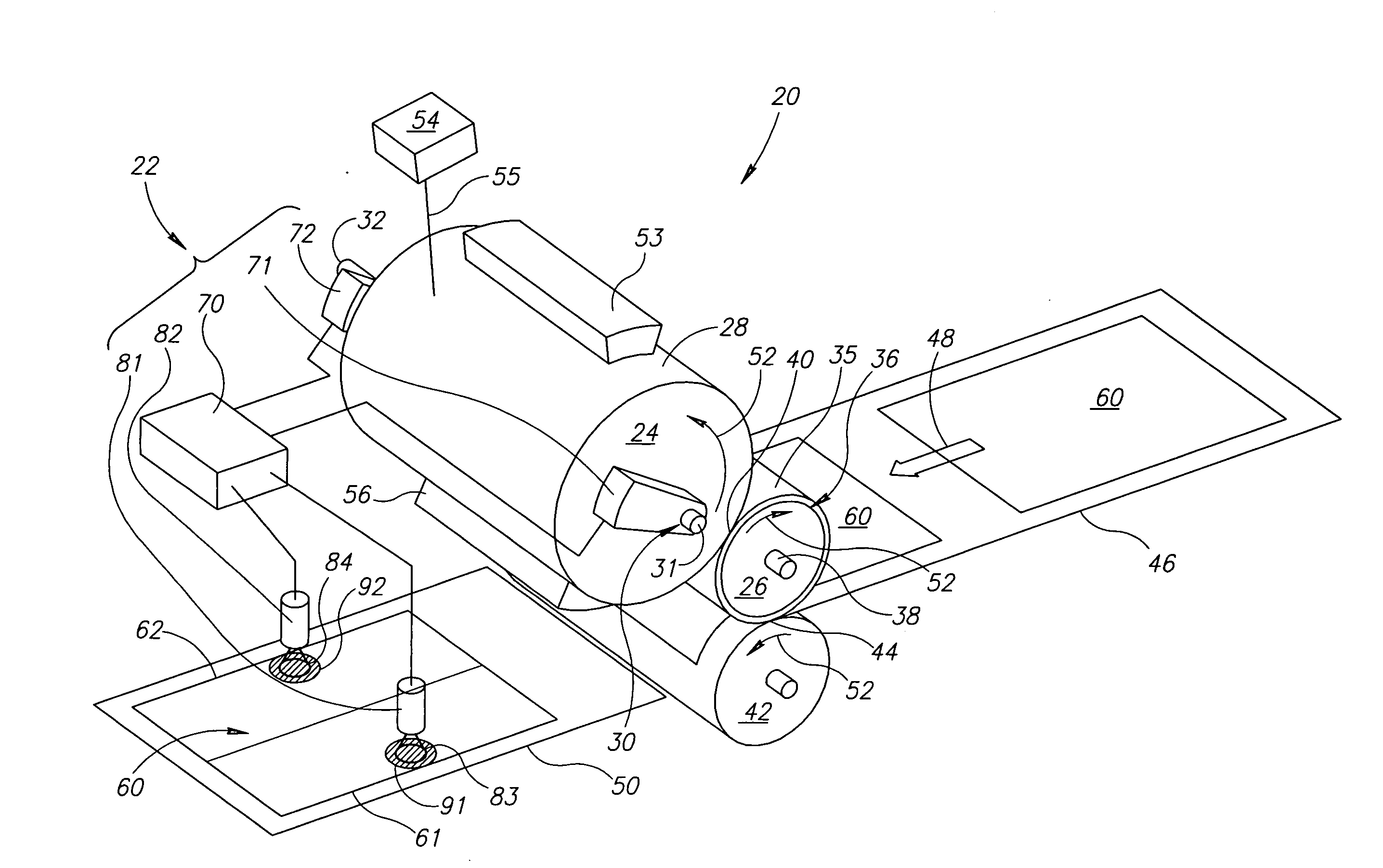
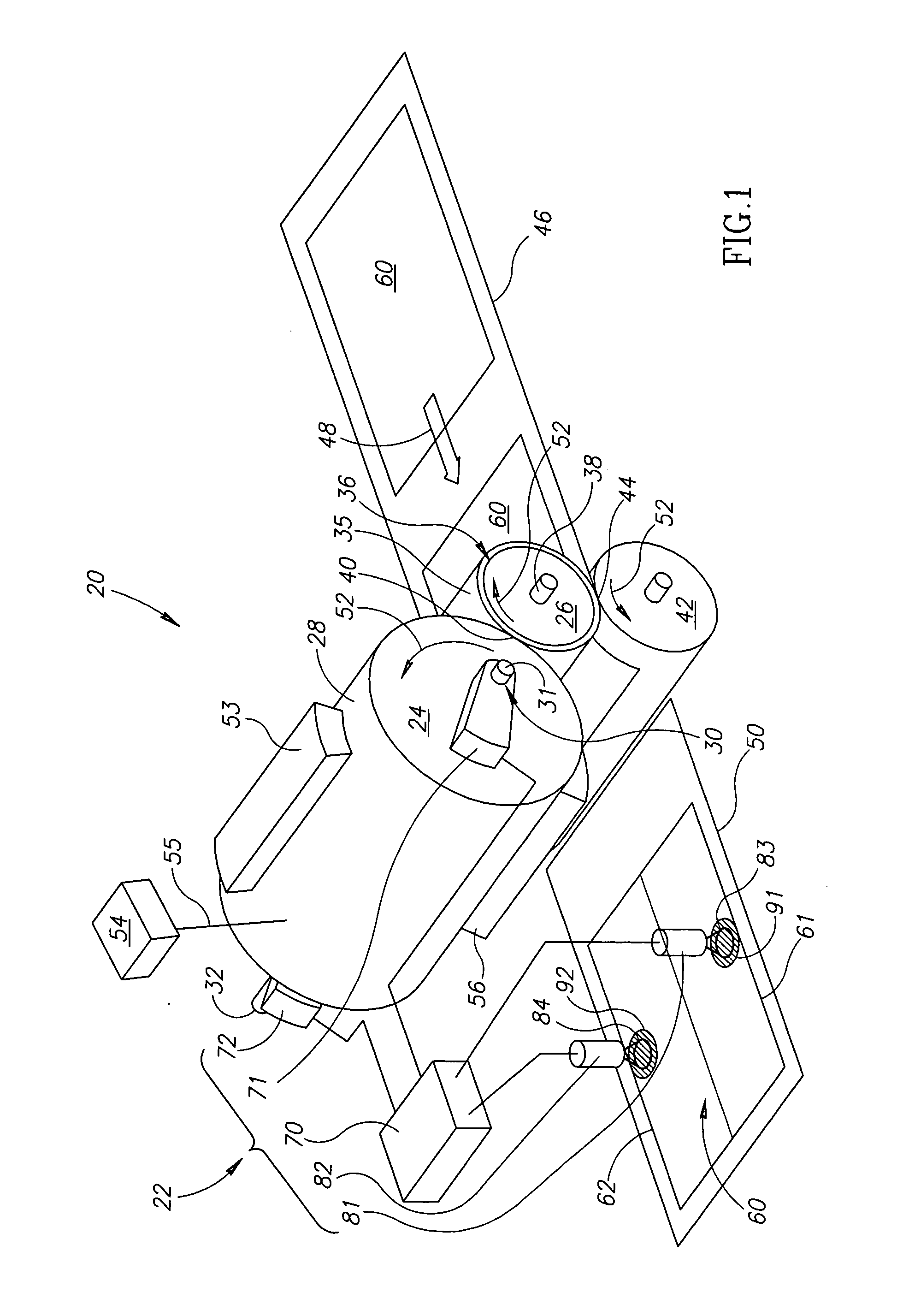
[0069]FIG. 1 schematically shows a digital printer 20 comprising pressure adjusting apparatus (PAA) 22 for automatically adjusting pressure between a photosensitive imaging cylinder (PIC) 24 and an intermediate transfer member (ITM) 26 comprised in the printer, in accordance with an embodiment of the present invention. Digital printer 20 is schematically shown operating in a pressure calibration mode during which PAA 22 automatically adjusts pressure between PIC 24 and ITM 26. FIG. 1 shows only elements and features of digital printer 20 that are germane to the discussion. Features and elements other than those shown in FIG. 1 may be present in the printer, and as various layouts and constructional features for printers are known in the art and the present invention is applicable to many types of printers, the printer may be different from that shown.

[0070] PIC 24 has a photosurface 28 and is optionally supported on a shaft 30 having ends 31 and 32, which is mounted to a suitable s...


PUM


Abstract

Apparatus for equalizing pressure along a nip between a photosensitive imaging cylinder (PIC) and an intermediate transfer member (ITM) in a printing press comprising: first and second optical sensors having first and second fields of view respectively that view different first and second regions of a substrate printed by the printer and generate signals responsive to the optical densities of first and second test patterns printed by the printer on the first and second regions of the substrate; at least one motor operable to control pressure between the rollers; and a controller that receives the signals and controls the at least one motor responsive to the signals to equalize the pressure along the nip.

Description

FIELD OF THE INVENTION [0001] The invention relates to printers and in particular to apparatus and methods of automatically adjusting pressure between rollers that transfer colorant in a printer in order to print an image on the substrate. BACKGROUND OF THE INVENTION [0002] To print an image on an appropriate substrate, a typical digital printer first forms a copy of the image, conventionally referred to as a “latent image”, on a photosensitive surface of a cylindrical roller, hereinafter referred to as a “photosensitive imaging cylinder” (PIC). To form the latent image a charger deposits a substantially constant charge density on the “photosurface”. The latent image is then formed by a laser that scans the charged photosurface and discharges regions thereon to generate a pattern of charged and uncharged pixels on the photosurface that replicates the image to be printed. A developer applies toner, hereinafter generically, toner, of desired color to the charged or the uncharged pixel...

Claims


Application Information

Patent Timeline
Patent Type & Authority Applications(United States)
IPC IPC(8): H01J40/14
CPCB41F33/0072B41P2233/50G03G15/5062G03G15/161B41P2233/51
Inventor HARUSH, SHLOMOGILA, OMERSHELEF, EYAL
Owner HEWLETT PACKARD INDIGO BV
Why Eureka
Try Eureka