Natural pan tilt zoom camera motion to preset camera positions

a natural pan tilt and camera technology, applied in the field of videoconferencing, can solve the problems of undesirable camera motion, too large images, less than pleasing aesthetic effect, etc., and achieve the effect of avoiding the undesirable effect of aesthetically pleasing and high zoom ratio

Active Publication Date: 2006-01-19
HEWLETT PACKARD DEV CO LP
View PDF35 Cites 28 Cited by
  • Summary
  • Abstract
  • Description
  • Claims
  • Application Information

AI Technical Summary

Benefits of technology

[0011] The system disclosed herein seeks to solve the problem of unnatural, dizzy camera motion when moving a camera between two preset positions, e.g., head and shoulder shots of two videoconference participants. Particularly, the system described herein attempts to mimic the camera movement that a professional camera operator would use in a professional video production. A preferred method of moving the camera between two positions is to first zoom out, away from the first position, pan across to the next position, then zoom in. This gives viewers of the camera content an idea of the spatial relationship between the two camera positions and also avoids the aesthetically undesirable effect of panning through irrelevant visual background at high zoom ratios. Disclosed herein is a technique of producing this desired behavior in the context of an automatically or semi-automatically controlled video camera, such as those used in conjunction with videoconferencing equipment.

Problems solved by technology

In many cases, two preset positions are not sufficiently close, making such camera motion is undesirable.
Often, this results in too large images of conference participants and / or other objects, which is a less than pleasing aesthetic effect.
While this technique does alleviate the undesirable aesthetic effect of the camera motion described in the preceding paragraph, it requires the intervention of a professional camera operator, which is frequently unavailable for most videoconferences and which adds significant expense to videoconferencing even if available.

Method used


Image

  • Natural pan tilt zoom camera motion to preset camera positions
  • Natural pan tilt zoom camera motion to preset camera positions
  • Natural pan tilt zoom camera motion to preset camera positions

Examples


Embodiment Construction

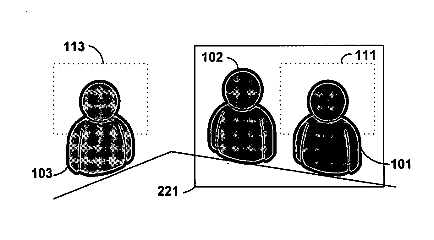
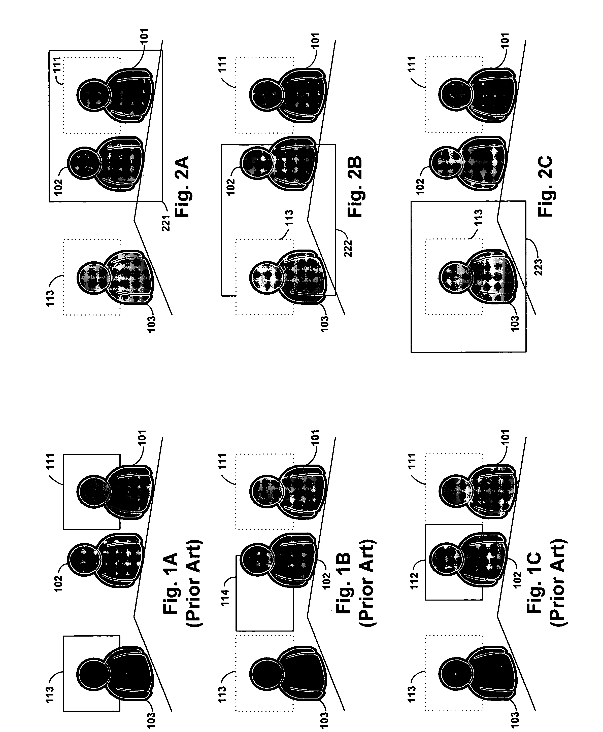
[0014] Clearer understanding of the prior art problem to which the system disclosed herein provides a solution may be better understood with reference to FIGS. 1A-1C. In each of these figures, one “endpoint” of a videoconference is depicted, comprising three conference participants 101, 102, and 103 seated around a conference table. To provide the most beneficial and aesthetically pleasing videoconference, multiple camera views may be defined, each corresponding to a particular camera pan angle, tilt angle, and zoom ratio. For example, an overall view might show the entire scene. Another typical camera view might be a head and shoulders close up of a conference participant, such as view 111 of participant 101 and view 113 of participant 103 depicted in FIG. 1A.

[0015] During the course of the videoconference, it will likely be necessary to move the camera from view 111 to view 113, for example, if participant 101 stopped speaking and participant 103 started speaking. As noted above,...


PUM


Abstract

The system disclosed herein seeks to solve the problem of unnatural, dizzy camera motion when moving a camera between two preset positions, e.g., head and shoulder shots of two videoconference participants. Particularly, the system described herein attempts to mimic the camera movement that a professional camera operator would use in a professional video production. A preferred method of moving the camera between two positions is to first zoom out, away from the first position, pan across to the next position, then zoom in. This gives viewers of the camera content an idea of the spatial relationship between the two camera positions and also avoids the aesthetically undesirable effect of panning through irrelevant visual background at high zoom ratios. Disclosed herein is a technique of producing this desired behavior in the context of an automatically or semi-automatically controlled video camera, such as those used in conjunction with videoconferencing equipment.

Description

BACKGROUND OF THE INVENTION [0001] 1. Field of the Invention [0002] The present invention relates generally to videoconferencing and more particularly to providing a method of improving the visual effect of moving a videoconferencing camera from one position (e.g., trained on a first videoconference participant) to a second position (e.g., a second video conference participant). [0003] 2. Description of Related Art [0004] Videoconferencing systems have become relatively widespread in commercial and other applications. One reason for the proliferation of videoconferencing is that it provides a level of interactivity comparable to face-to-face meeting without the attendant expense of travel for conference participants that are not in the same physical location. The effectiveness of videoconferencing depends in part on providing an experience to the user that is comparable to face-to-face meeting. One way is which this is performed is through controlling the view of the videoconferenci...

Claims


Application Information

Patent Timeline
Patent Type & Authority Applications(United States)
IPC IPC(8): H04N7/14
CPCH04N7/15
Inventor NIMRI, ALAINSHAO, JUNQING
Owner HEWLETT PACKARD DEV CO LP
Why Eureka
Try Eureka