Network protector added load ability through forced convection

a network protector and load ability technology, applied in the field of network protectors, can solve the problem of increasing the amount of heat lost through convection, and achieve the effect of increasing the amount of heat los

Inactive Publication Date: 2006-01-19
EATON CORP
View PDF15 Cites 7 Cited by
  • Summary
  • Abstract
  • Description
  • Claims
  • Application Information

AI Technical Summary

Problems solved by technology

The increased fluid flow over the buses increases the amount of heat lost though convection.

Method used


Image

  • Network protector added load ability through forced convection
  • Network protector added load ability through forced convection
  • Network protector added load ability through forced convection

Examples


Embodiment Construction

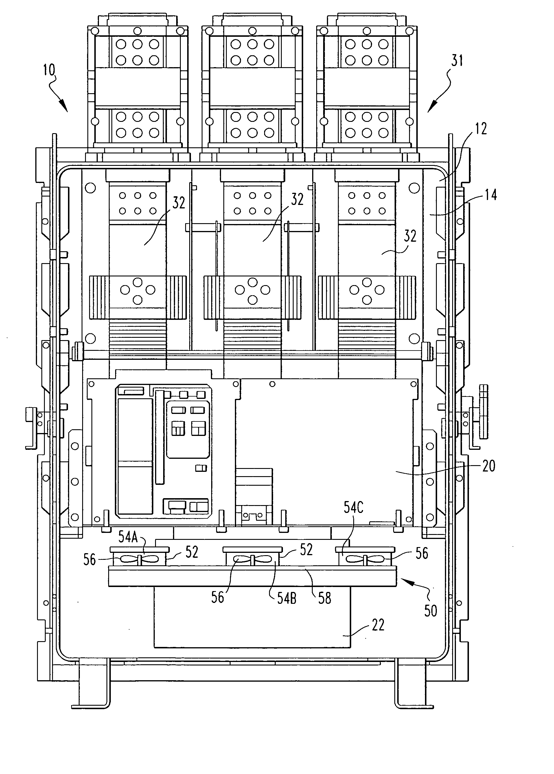
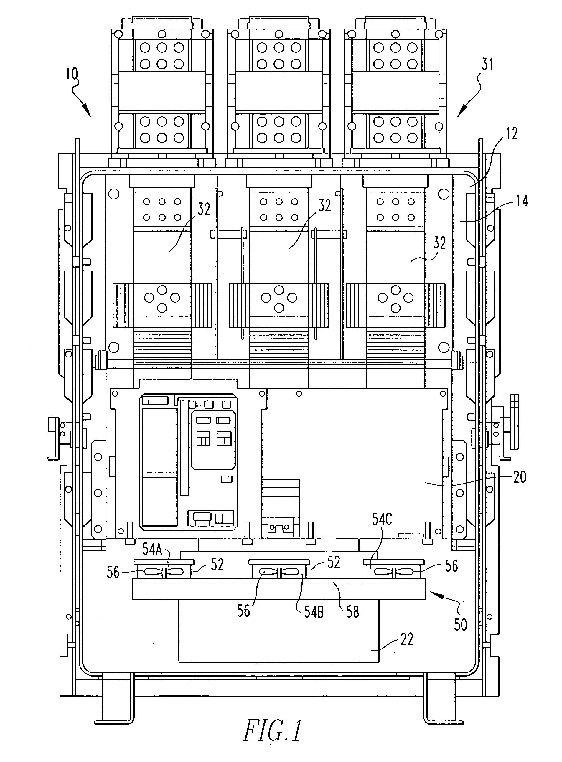
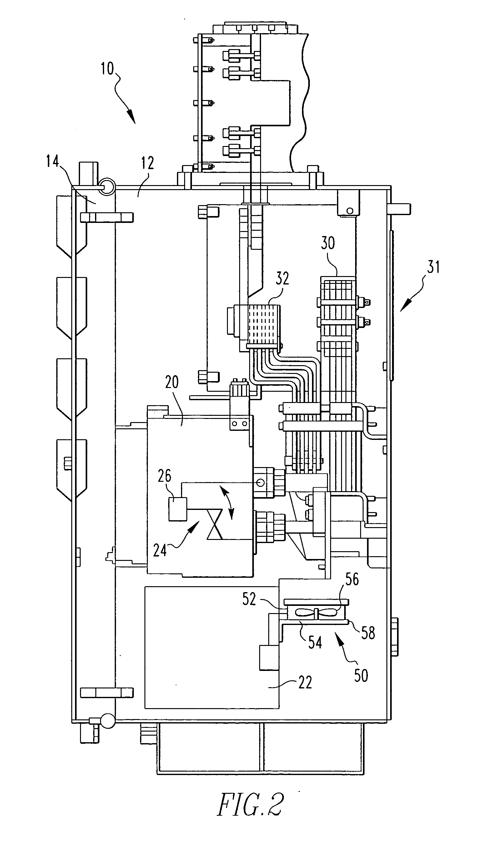
[0016] As shown in FIGS. 1 and 2, a network protector 10 includes a housing assembly 12 structured to form an enclosure with a movable door 14. The housing assembly 12 is structured to be placed within a vault 16. A vault 16 is typically made of concrete or a similar material. The two primary network protector components, a circuit breaker 20 and a control assembly 22 are disposed within the housing assembly 12. The circuit breaker 20 includes at least one set of main contacts 24 (shown schematically, FIG. 2) that are structured to move between a first, open position and a second, closed position. When the main contacts 24 are in the second, closed position, electricity may flow through the circuit breaker 20. When the main contacts 24 are in the first, open position, electricity cannot flow through the circuit breaker 20. The circuit breaker 20 also includes an operating mechanism 26 (shown schematically) that is structured to move the main contacts 24 between the first and second ...


PUM


Abstract

A network protector that includes a housing assembly, a circuit breaker, a control assembly, and a convention cooling assembly. The housing assembly is structured to form an enclosure and has a bus assembly coupled to an interior wall. The circuit breaker is structured to engaged the bus assembly within the housing assembly. The convection cooling assembly is coupled to the housing assembly and is structured to move air over the bus assembly.

Description

BACKGROUND OF THE INVENTION [0001] 1. Field of the Invention [0002] The present invention relates to network protectors and, more specifically, to a network protector having a convection cooling assembly disposed within the network protector housing. [0003] 2. Background Information [0004] Secondary power distribution networks consist of interlaced grids which are supplied by two or more sources of power so that the loss of a single source of power will not result in an interruption of service. Such networks provide the highest level of reliability possible with conventional power distribution and are normally used to supply high-density load areas such as a section of a city, a large building, or an industrial site. Between the power sources and the network are a transformer and a network protector. Such network protectors are often found in dust-proof or moisture-proof housings which are disposed in subterranean passageways in large metropolitan areas. The housing, or “tank,” may ...

Claims


Application Information

Patent Timeline
Patent Type & Authority Applications(United States)
IPC IPC(8): H05K7/20
CPCH01H71/123H01H9/52H02B1/565
Inventor JUR, ARTHUR JAMESBRANDT, DOUGLAS MICHAELDAVIS, KEVIN MICHAEL
Owner EATON CORP
Why Eureka
Try Eureka