Fused terminal for use with a network protector

a network protector and fuse terminal technology, applied in the direction of overvoltage protection resistors, emergency protective arrangements for limiting excess voltage/current, and arrangements responsive to excess voltage, etc., can solve the problem of affecting the service life of the customer, and affecting the service life of the primary feeder

Inactive Publication Date: 2002-03-19
RICHARDS MFG CO INC
View PDF4 Cites 3 Cited by
  • Summary
  • Abstract
  • Description
  • Claims
  • Application Information

AI Technical Summary

Problems solved by technology

In New York, and in other major cities throughout North America, electricity is distributed from a utility company to customers via an electrical network; an electrical network being the most reliable, but also the most expensive method of electrical distribution.
Because a number of transformer secondaries are tied together, an electrical fault on one of the transformers or one of the high voltage feeders does not deprive the customer of electricity.
The major disadvantage is that, because the transformer secondaries are tied together, absent some form of sectionalizing device, a fault on any one of the primary feeders would have disastrous consequences.
This would result in customer power outages.
When the network protector is operating correctly, a fault on its primary feeder will cause the network protector to open.
Fuses are installed on the secondary-side network of the network protector such that if the network protector fails to open when necessary, the feeder can be grounded causing those fuses to blow.
Despite this fact, such a fault can have damaging consequences.
It can cause large quantities of current to flow into the secondary-side network towards the fault.
The heat generated by these large quantities of current may reach a level at which the network protector or the transformer is severely damaged.
If current through the fuse reaches a certain level, these fuses will blow and damage will be averted.
However, internal fuses radiate a significant amount of heat.
The heat generated by the internal fuses thus represents a limitation on the current-carrying capacity of a network protector.
Internal fuses may also lead to damage to the network protector.
Problems result when severe secondary faults result in a rapid rise in the quantity of current flowing through the network protectors.
The fuses may then blow violently spraying molten copper throughout the interior of the network protector housing.
In addition to being messy, on 277 / 480 volt network protectors, this can result in damage due to arcing in the network protector housing.

Method used


Image

  • Fused terminal for use with a network protector
  • Fused terminal for use with a network protector
  • Fused terminal for use with a network protector

Examples


Embodiment Construction

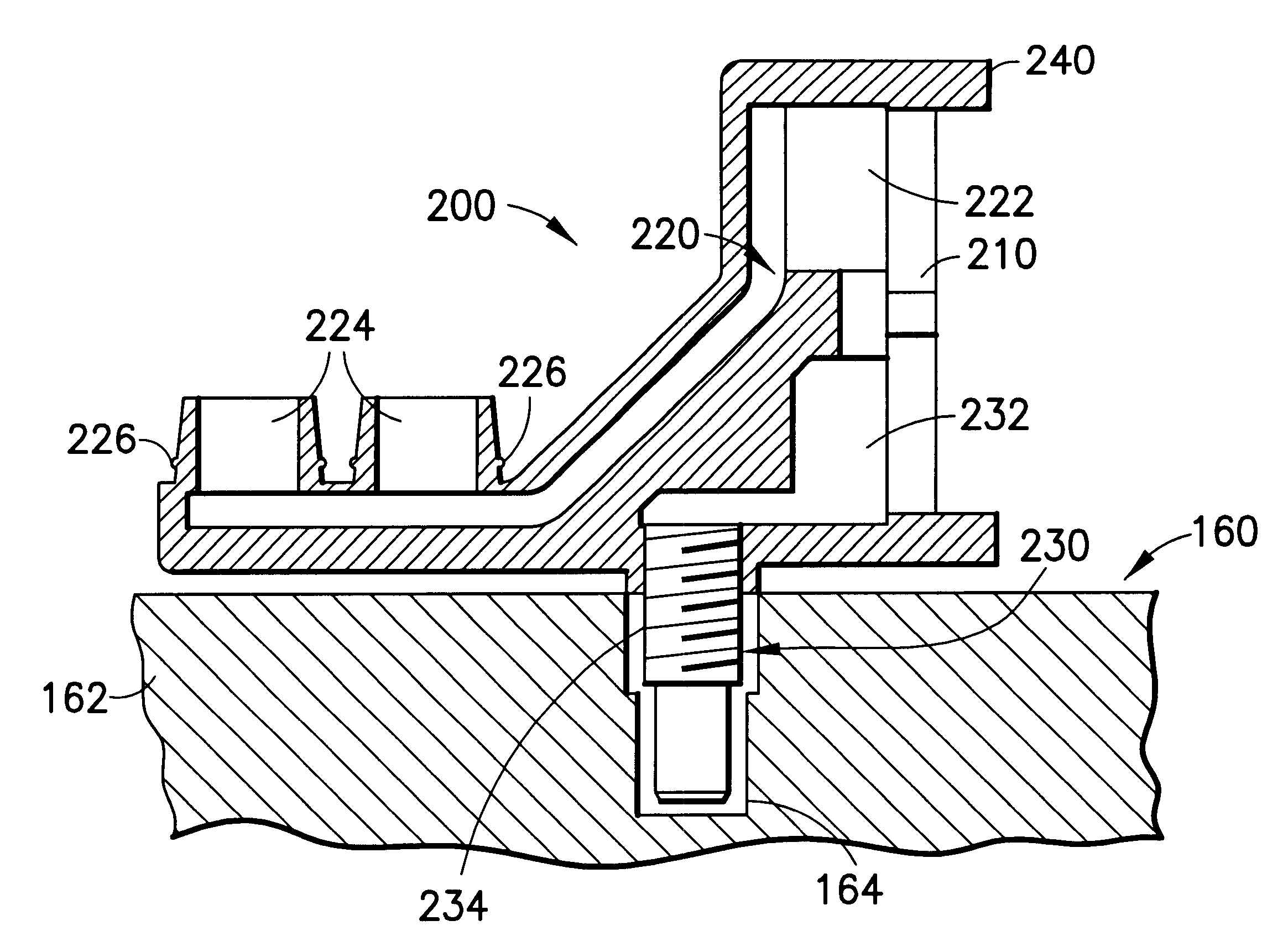
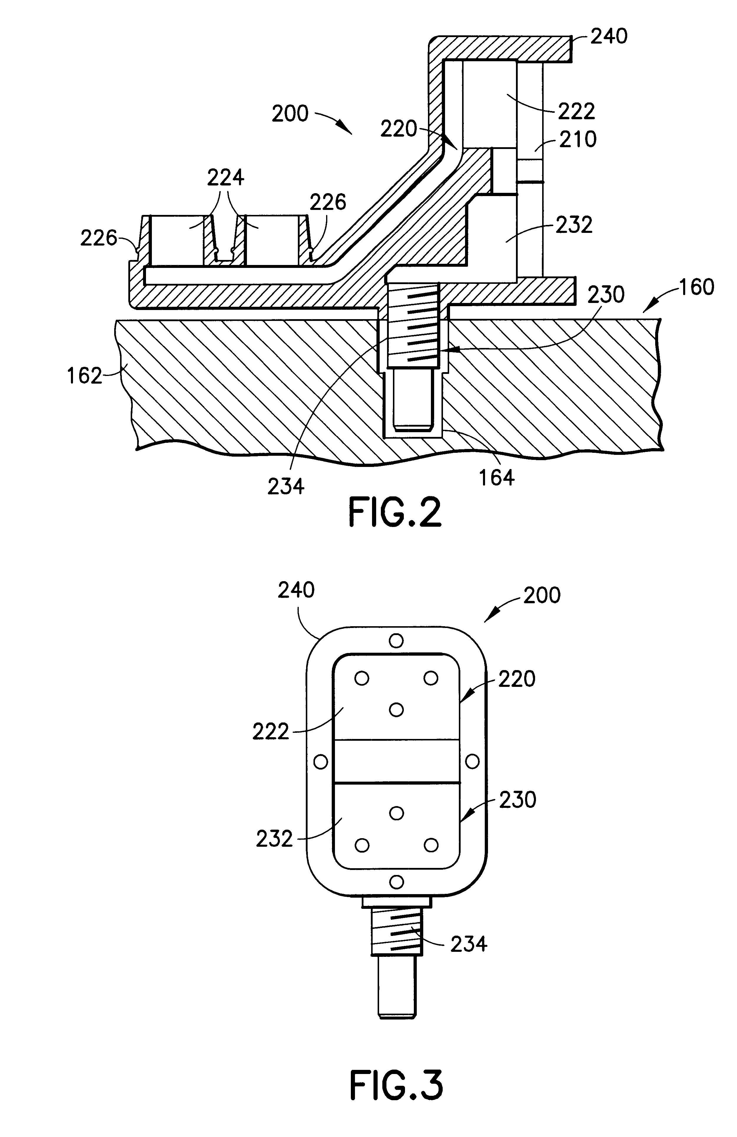
The present invention is directed to a terminal for a network protector that includes an integral fuse and that may be located outside of the network protector housing.

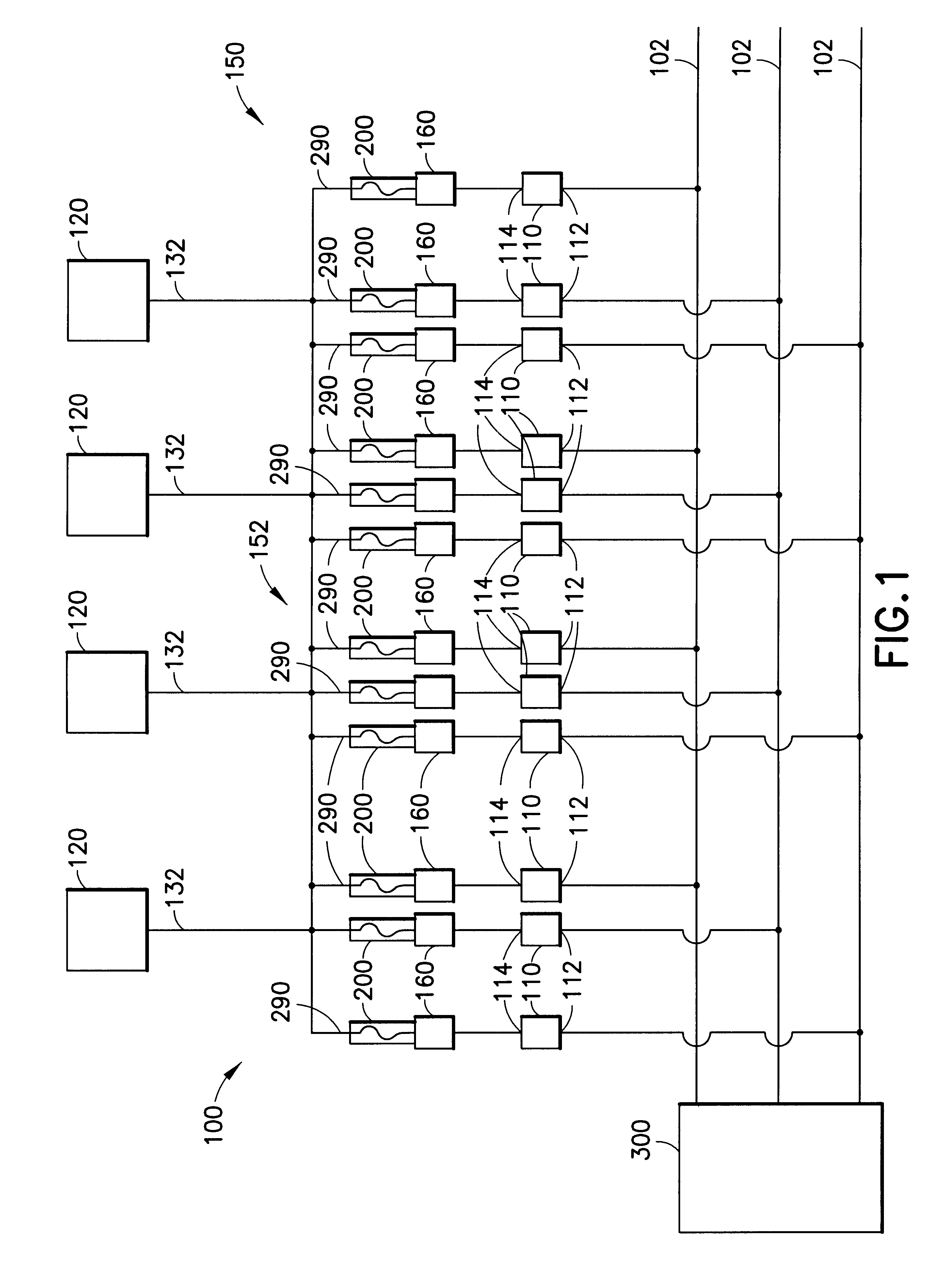
Referring now to the drawings in detail, FIG. 1 schematically depicts an electrical network 100 including a plurality of high-voltage primary feeder cables 102 connected to a utility company 300 that generates and provides power to the plurality of feeder cables 102. The electrical network 100 also includes a secondary-side network 150 that provides power to a plurality of utility customers 120. The secondary-side network 150 includes a plurality of low-voltage feeder cables 132 that run from a grid 152 directly to the customers 120.

Various devices are provided to interface between the feeder cables 102 and secondary-side network 150. A step-down transformer 110 is provided to step-down the high-voltage being carried on the primary feeder cables 102 to a voltage that may be used directly by the customers 120. For exam...


PUM


Abstract

A fused terminal for use with a network protector, the disconnect terminal including an integral fuse and being located outside of the network protector housing and not substantially increasing the overall height of the network protector.

Description

BACKGROUND OF INVENTIONThe present invention is directed to power distribution connectors and, more particularly, to a terminal for a network protector having an integral fuse.In New York, and in other major cities throughout North America, electricity is distributed from a utility company to customers via an electrical network; an electrical network being the most reliable, but also the most expensive method of electrical distribution. The electrical network generally consists of utility company high voltage sub-stations and distribution wiring, generally consisting of a number of high voltage cables called primary feeders (e.g., 13,800 volts) running in ducts under the city's streets. Various devices and interfaces connect the utility company and a customer such as, for example, a step-down transformer to step-down the voltage level generated and provided by the utility company and to ensure continued electrical service to the customer. At various points along the street the utili...

Claims


Application Information

Patent Timeline
Patent Type & Authority Patents(United States)
IPC IPC(8): H01H85/044H01H85/00H01H9/00H01H85/20H01H9/10
CPCH01H85/044H01H9/10H01H2085/206H01H85/205
Inventor BIER, BRUCE
Owner RICHARDS MFG CO INC
Why Eureka
Try Eureka