Locking hinge connector apparatus

Inactive Publication Date: 2006-01-26
BLACKMAN GARY PALMER +1
View PDF34 Cites 39 Cited by
  • Summary
  • Abstract
  • Description
  • Claims
  • Application Information

AI Technical Summary

Benefits of technology

[0011] The apparatus is designed to simultaneously reduce back strain and fatigue and increase the effec

Problems solved by technology

However, such common fixed-direction pole attachment devices are typically limited to a single orientation of usage, some of which may not be feasible for certain desired operation

Method used


Image

  • Locking hinge connector apparatus
  • Locking hinge connector apparatus
  • Locking hinge connector apparatus

Examples


Embodiment Construction

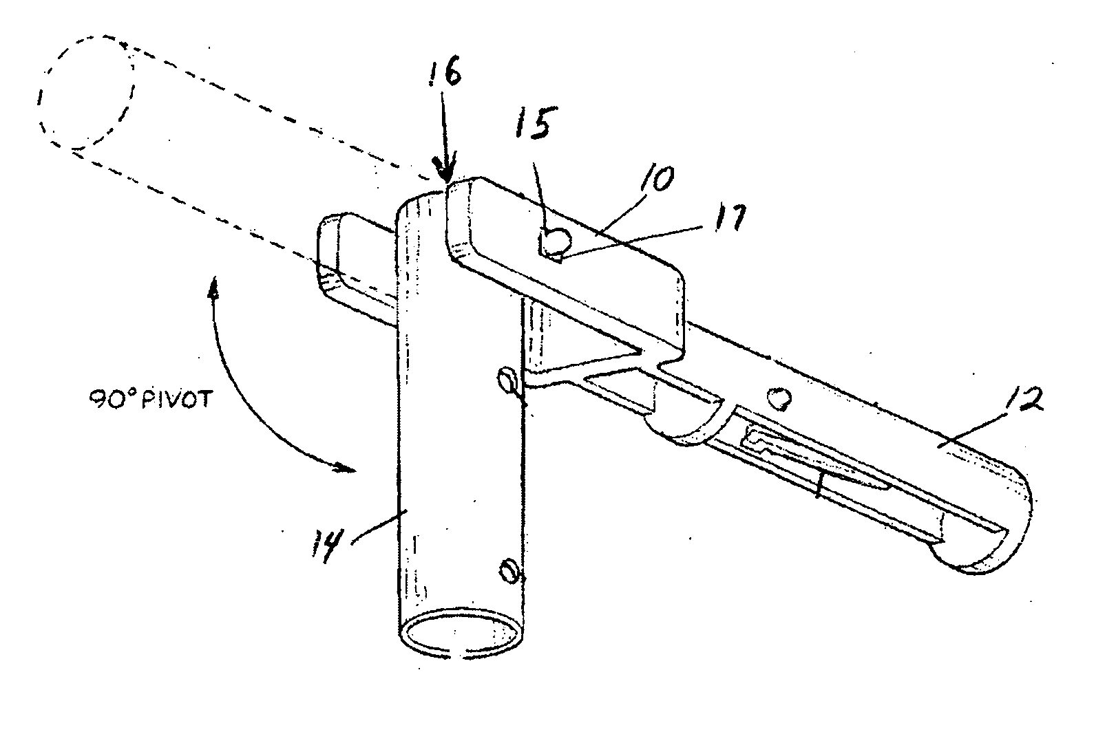
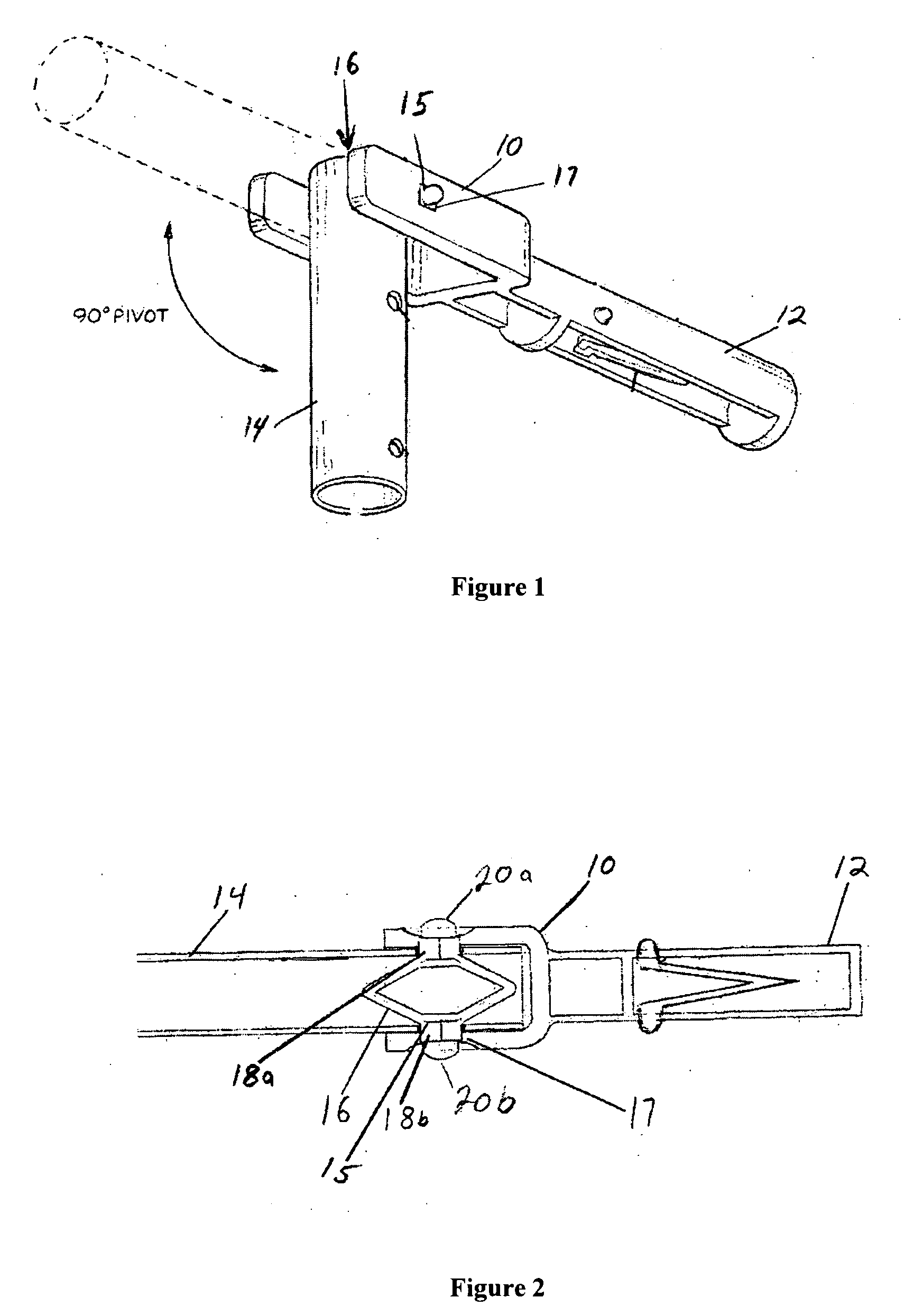
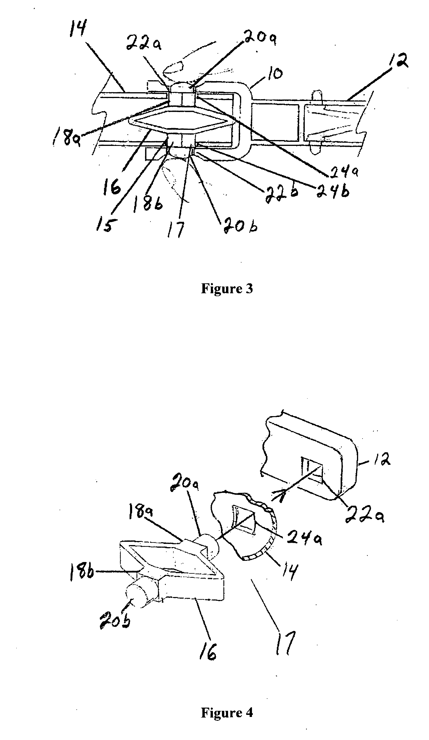
[0053] A locking hinge connector apparatus 10 as shown in FIG. 1 comprises two main connector parts 12 and 14, pivotally joined by a hinge mechanism 15 which in some embodiments can be integrally incorporated with a spring mechanism 16, enabling the first connector part 12 of the apparatus 10 to be pivoted into an angled orientation position relative to the second connector part 14. The hinge mechanism 15 need not be composed of the same part as the spring mechanism 16, although in this embodiment both are integral within a single plastic part as depicted in FIG. 1. Together with the hinge mechanism 15 the connector apparatus 10 can further include an integral locking mechanism 17, also known as a locking / unlocking mechanism, such that the hinge between the two main connector parts 12 and 14 can be locked or unlocked, and while unlocked can be pivoted into a desired relative orientation and then locked into place to prevent relative pivoting of the two main connector parts, until un...


PUM


Abstract

A connector apparatus which comprises two main connector parts, pivotally joined by a hinge mechanism, enabling a first part of the connector apparatus to be pivoted into an angled orientation position relative to the second connector part. Together with a hinge mechanism the connector apparatus can include an integral locking mechanism, such that the two main connector parts can be pivoted into a desired relative orientation and then locked into place. The user can easily unlock, pivot, and then lock the hinge mechanism in a desired relative orientation, allowing the device to be switched between straight, and angled orientations very quickly. In one embodiment, a connector apparatus is made to attach a pole handle, such as a swimming pool cleaning apparatus handle, on the first main connector part, and where the second main connector part attaches to a swimming pool skimmer net or brush.

Description

RELATED APPLICATIONS [0001] This Utility Patent Application for “Locking Hinge Connector Apparatus” filed on Jun. 29, 2005 is a Continuation-in-Part to U.S. Provisional Patent Applications Nos. 60 / 585,247 filed Jul. 1, 2004 and 60 / 667,909 filed Mar. 25, 2005 and claims the benefit of the priority dates of those two U.S. Provisional Patent Applications. The aforementioned U.S. Provisional Patents Applications Nos. 60 / 585,247 and 60 / 667,909 hereby incorporate by reference in their entirety and for all purposes into this Patent Application. [0002] This Patent Application filed on Jun. 29, 2005 is also hereby cross-referenced to and incorporates by reference the separate Utility Patent Application titled, “Quick Change Pole End Attachment Connector” invented by the same two co-inventors Gary Blackman and Kent Zilliox, and filed on the same date of filing with the present Patent Application for “Locking Hinge Connector Apparatus.”FIELD OF THE INVENTION [0003] The present invention relate...

Claims


Application Information

Patent Timeline
IPC IPC(8): E05D15/50
CPCA46B5/0075A46B17/02B25G1/04Y10T16/528E04H4/1609E05D11/1007F16C11/10B25G1/06
Inventor BLACKMAN, GARY PALMERZILLIOX, KENT BRIAN
Owner BLACKMAN GARY PALMER
Why Eureka
Try Eureka