Imaging optical system and imaging lens device

a technology of optical system and lens device, which is applied in the field of imaging optical system and imaging lens device, can solve the problems of user failure to release the shutter at the right moment, a certain time to finalize the shooting preparation operation, and increase the cost of the imaging optical system, etc., and achieve the effect of compact imaging optical system and low cos

Inactive Publication Date: 2006-01-26
KONICA MINOLTA OPTO
View PDF10 Cites 99 Cited by
  • Summary
  • Abstract
  • Description
  • Claims
  • Application Information

AI Technical Summary

Benefits of technology

[0021] In this imaging optical system, the two reflecting prisms each adapted for bending the incident light at the predetermined angle for reflection are arranged in such a manner that the incident surface of the reflecting prism dis

Problems solved by technology

In the imaging optical system adopting the collapsible mechanism, the construction of a lens barrel is complicated, which may give rise to cost increase.
Particularly, in a mechanism constructed such that a lens unit pops out in response to turning on of the power of the digital apparatus, it takes a certain time to finalize a shooting preparatory operation.
Accordingly, a user may fail to release the shutter at a right moment to capture a scene.
Decentered aberrations are likely to occur in a decentered optical system unlike an axially symmetrical optical system.
Accordingly, a conventional facility for use in production and evaluation of axially symmetrical optical systems cannot be used for a decentered optical system, and a new facility is required.
Further, since a multitude of aberrations to be corrected occur in the decentered optical system, it is extremely difficult to produce an imagi

Method used


Image

  • Imaging optical system and imaging lens device
  • Imaging optical system and imaging lens device
  • Imaging optical system and imaging lens device

Examples


first embodiment

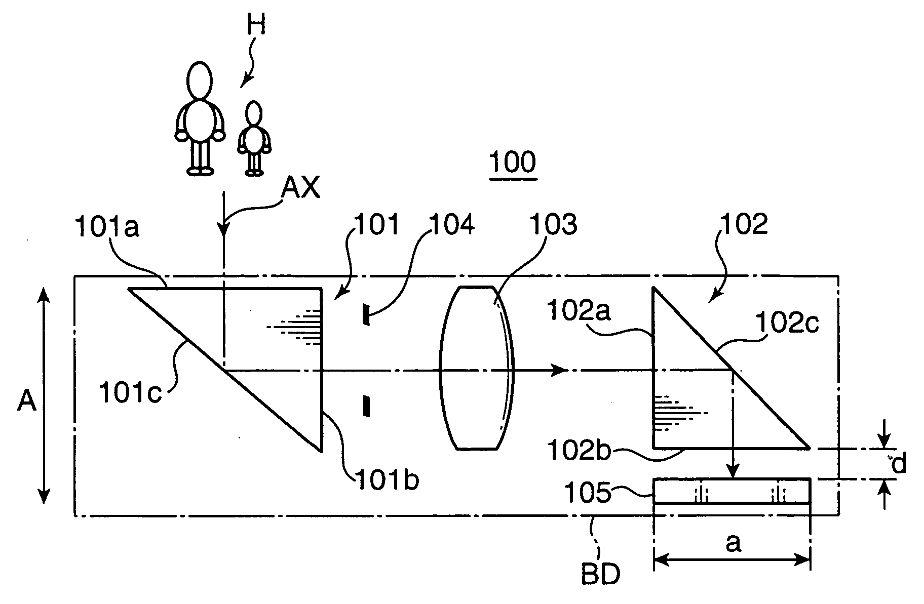
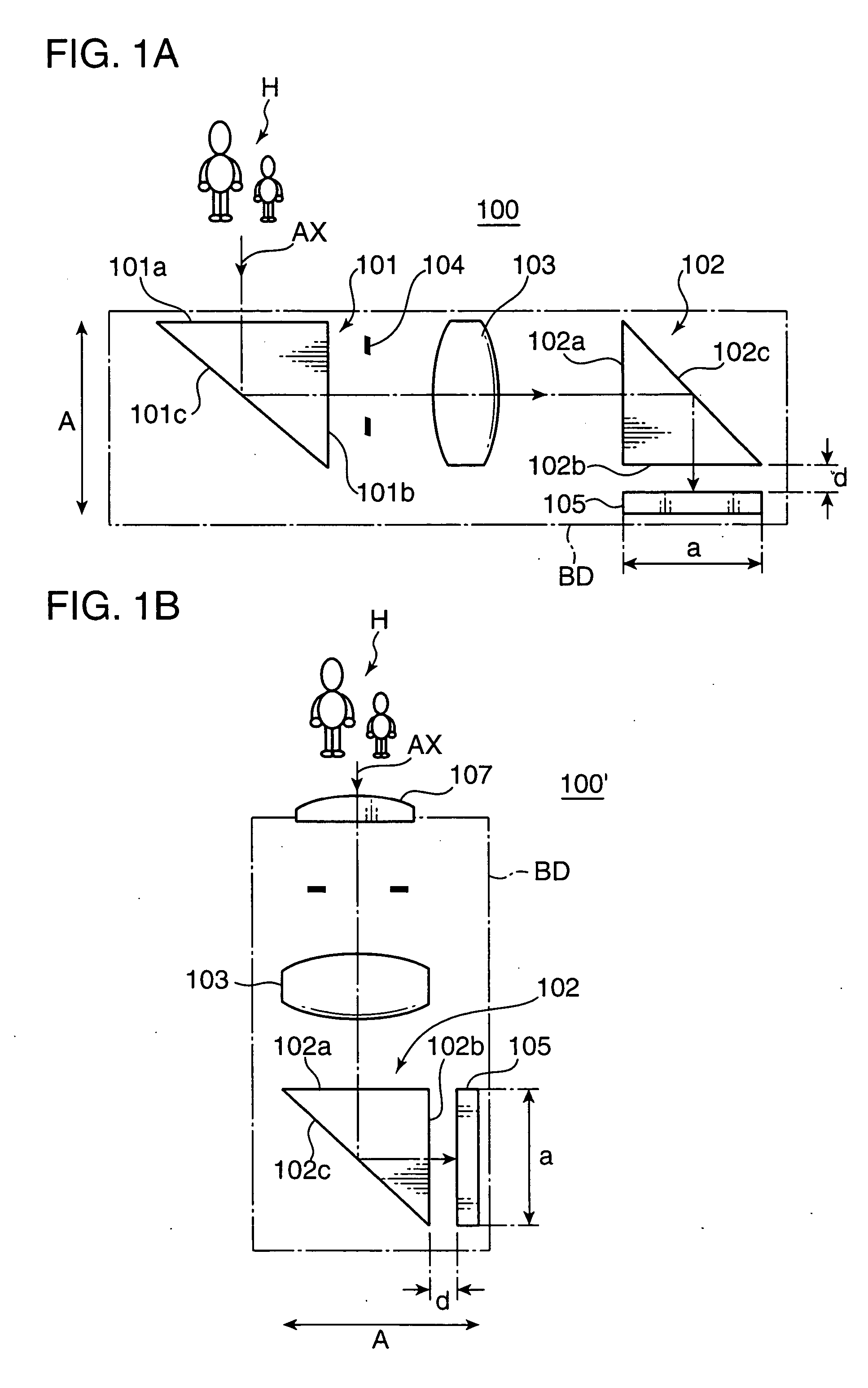
[0124]FIG. 11 is a cross-sectional view of an arrangement of an imaging optical system 51 as a first embodiment taken along a longitudinal direction of the optical axis (AX) in FIG. 11. As shown in FIG. 11, the imaging optical system 51 has, from the object side along the optical path, a first reflecting prism 1 having a positive optical power as a whole, which corresponds to the incident side prism 101 shown in FIG. 1A, an aperture stop (ST) for regulating the light amount, a first lens element 2 having a positive optical power, a second lens element 3 having a negative optical power, and a second reflecting prism 4 having a positive optical power as a whole, which corresponds to the imaging side prism 102 shown in FIG. 1A. A plane parallel plate 5 and an image sensor 6 are arranged on the side of the second reflecting prism 4 opposite to the second lens element 3.

[0125]FIG. 11, as well as FIGS. 14 and 16 respectively showing a second embodiment and a third embodiment of the inven...

second embodiment

[0132]FIG. 14 is a cross-sectional view of an arrangement of an imaging optical system 52 as a second embodiment taken along a longitudinal direction of the optical axis (AX) in FIG. 14. As shown in FIG. 14, the imaging optical system 52 has, from the object side along the optical path, an aperture stop (ST) for regulating the light amount, a first reflecting prism 7 having a positive optical power as a whole, a first lens element 8 having a negative optical power, and a second reflecting prism 9 having a positive optical power as a whole.

[0133] The first reflecting prism 7 has an incident surface 7a of a positive optical power, an exit surface 7b of a positive optical power, and a planar reflecting surface RL3 arranged on the optical path between the incident surface 7a and the exit surface 7b. The second reflecting prism 9 has an incident surface 9a of a positive optical power, an exit surface 9b of a negative optical power, and a planar reflecting surface RL4 arranged on the opt...

third embodiment

[0135]FIG. 16 is a cross-sectional view of an arrangement of an imaging optical system 53 as a third embodiment taken along a longitudinal direction of the optical axis (AX) in FIG. 16. As shown in FIG. 16, the imaging optical system 53 has, from the object side along the optical path, a first reflecting prism 10 having a positive optical power as a whole, an aperture stop (ST) for regulating the light amount, a first lens element 11 having a positive optical power, a second lens element 12 having a negative optical power, and a second reflecting prism 13 having a positive optical power as a whole.

[0136] The first reflecting prism 10 has an incident surface 10a of a negative optical power, an exit surface 10b of a positive optical power, and a planar reflecting surface RL5 arranged on the optical path between the incident surface 10a and the exit surface 10b. The second reflecting prism 13 has an incident surface 13a of a negative optical power, an exit surface 13b of a positive op...


PUM


Abstract

An imaging optical system 100 has an imaging side prism 102 for bending incident light at about 90 degrees for reflection, and an image sensor 105 having a light receiving surface opposing to an exit surface 102b of the imaging side prism 102. At least one of an incident surface 101a of an incident side prism 101 and an incident surface 101a of the imaging side prism 102, or at least one of an exit surface 101b of the incident side prism 101 and the exit surface 102b of the imaging side prism 102 has an optical power. An arrangement relation between the exit surface 102b of the imaging side prism 102 and the image sensor 105 is established to satisfy the conditional formula (1):
0.0≦d/a<0.8   (1)
where d represents a distance between the exit surface 102b and the light receiving surface of the image sensor 105, and a represents a height of the light receiving surface of the image sensor 105 on a plane where an optical path of the imaging optical system 100 is folded, e.g., the size of the image sensor 105 in the shorter side direction thereof. This arrangement enables to reduce the thickness of an apparatus housing BD for incorporating the imaging optical system 100.

Description

[0001] This application is based on Japanese Patent Application Nos. 2004-216517, 2004-315771, 2005-38323, and 2005-41203 respectively filed on Jul. 23, 2004, Oct. 29, 2004, Feb. 15, 2005, and Feb. 17, 2005 the contents of which are hereby incorporated by reference. BACKGROUND OF THE INVENTION [0002] 1. Field of the Invention [0003] The present invention relates to an imaging optical system, and an imaging lens device incorporated with the imaging optical system. [0004] 2. Description of the Related Art [0005] In recent years, with an explosive spread of digital apparatuses such as a digital still camera, a digital video camera, a mobile phone with a built-in camera (hereinafter, called as “camera phone”), and a personal digital assistant (PDA), development of a high-resolution or sophisticated image sensor to be loaded in these digital apparatuses has been rapidly progressed. In view of this, high optical performance is demanded for an imaging optical system for guiding an optical ...

Claims


Application Information

Patent Timeline
IPC IPC(8): H04N5/225
CPCG02B13/0025G02B13/003G02B13/0035H04N5/2254G02B13/0065G02B13/007G02B13/006H04N23/55
Inventor KONNO, KENJIOHZAWA, SOHISHIHARA, JUNSHIMO, MITSUAKIKIBAYASHI, HIROSHI
Owner KONICA MINOLTA OPTO
Why Eureka
Try Eureka