Zoom lens system, imaging apparatus and method for varying focal length

a zoom lens and imaging apparatus technology, applied in the field of zoom lens systems, imaging apparatus and methods for varying focal lengths, can solve problems such as difficulty in obtaining preferable optical performance over the entire zoom range, and achieve the effect of high optical performan

Inactive Publication Date: 2008-01-03
NIKON CORP
View PDF10 Cites 4 Cited by
  • Summary
  • Abstract
  • Description
  • Claims
  • Application Information

AI Technical Summary

Benefits of technology

[0009] The present invention is made in view of the aforementioned problems and has an object to provide a zoom lens system that is inexpensive, compact and lightweight with high optical performance, and to provide an imaging apparatus and a method for varying a focal length of the zoom lens system.

Problems solved by technology

Although the conventional zoom lens system has a wide angle of view and a given zoom ratio as a standard zoom lens system and is compact and lightweight with a reasonable price, it has been difficult to obtain preferable optical performance over entire zoom range.

Method used


Image

  • Zoom lens system, imaging apparatus and method for varying focal length
  • Zoom lens system, imaging apparatus and method for varying focal length
  • Zoom lens system, imaging apparatus and method for varying focal length

Examples


example 1

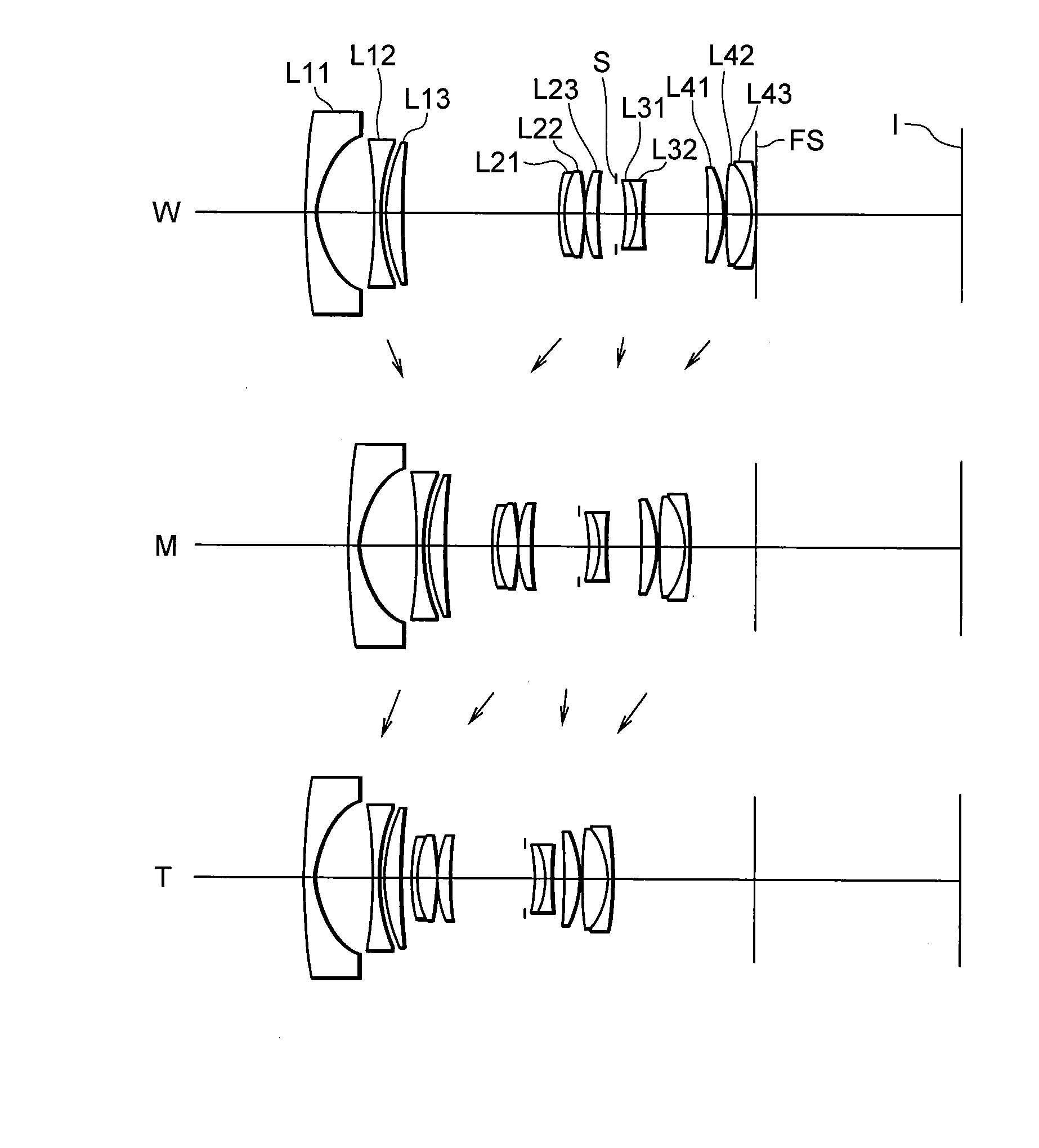
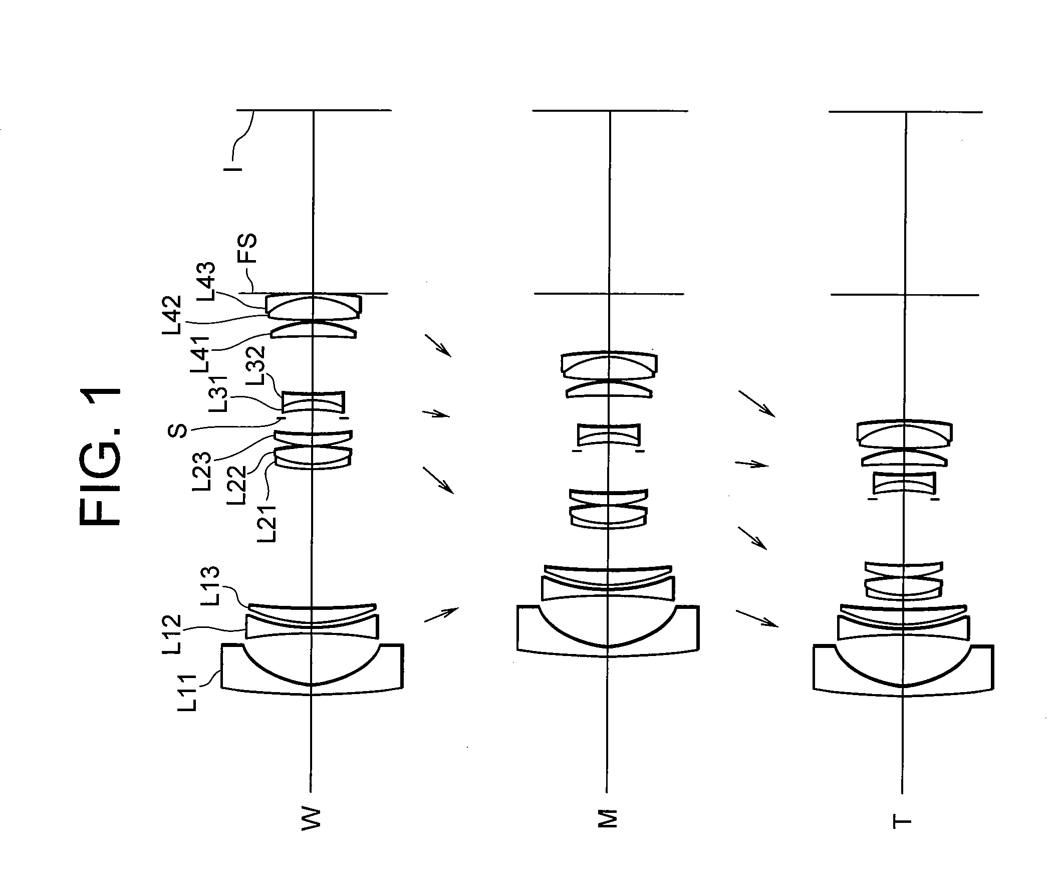
[0090]FIG. 1 is a diagram showing a lens configuration of a zoom lens system according to Example 1.

[0091] The zoom lens system according to Example 1 is composed of, in order from an object, a first lens group G1 having negative refractive power, a second lens group G2 having positive refractive power, a third lens group G3 having negative refractive power, and a fourth lens group G4 having positive refractive power.

[0092] The first lens group G1 is composed of, in order from the object, a negative meniscus lens L11 having a convex surface facing the object, a double concave negative lens L12, and a positive meniscus lens L13 having a convex surface facing the object.

[0093] The second lens group G2 is composed of, in order from the object, a cemented positive lens constructed by a negative meniscus lens L21 having a convex surface facing the object cemented with a double convex positive lens L22, and a positive meniscus lens L23 having a convex surface facing the object.

[0094] ...

example 2

[0113]FIG. 3 is a diagram showing a lens configuration of a zoom lens system according to Example 2.

[0114] The zoom lens system according to Example 2 is composed of, in order from an object, a first lens group G1 having negative refractive power, a second lens group G2 having positive refractive power, a third lens group G3 having negative refractive power, and a fourth lens group G4 having positive refractive power.

[0115] The first lens group G1 is composed of, in order from the object, a negative meniscus lens L11 having a convex surface facing the object, and a cemented negative lens constructed by a double concave negative lens L12 cemented with a double convex positive lens L13.

[0116] The second lens group G2 is composed of, in order from the object, a cemented positive lens constructed by a negative meniscus lens L21 having a convex surface facing the object cemented with a double convex positive lens L22, and a positive meniscus lens having a convex surface facing the obj...

example 3

[0125]FIG. 5 is a diagram showing a lens configuration of a zoom lens system according to Example 3.

[0126] The zoom lens system according to Example 3 is composed of, in order from an object, a first lens group G1 having negative refractive power, a second lens group G2 having positive refractive power, a third lens group G3 having negative refractive power, and a fourth lens group G4 having positive refractive power.

[0127] The first lens group G1 is composed of, in order from the object, a negative meniscus lens L11 having a convex surface facing the object, and a cemented negative lens constructed by a double concave negative lens L12 cemented with a positive meniscus lens L13 having a convex surface facing the object.

[0128] The second lens group G2 is composed of, in order from the object, a double convex positive lens L21, and a cemented positive lens constructed by a double convex positive lens L22 cemented with a double concave negative lens L23.

[0129] The third lens group...


PUM


Abstract

Providing a zoom lens system being inexpensive, compact and lightweight with high optical performance, and an imaging apparatus, and a method for varying a focal length. The zoom lens system includes, in order from an object, a first lens group having negative refractive power, a second lens group having positive refractive power, a third lens group having negative refractive power, and a fourth lens group having positive refractive power. Upon zooming from a wide-angle end state to a telephoto end state, a distance between the first and second lens groups decreases, a distance between the second and third lens groups increases, and a distance between the third and fourth lens groups decreases. The second lens group consists of two positive lenses or less and one negative lens. The fourth lens group consists of two positive lenses or less and one negative lens. Given conditions are satisfied.

Description

[0001] The disclosure of the following priority applications are herein incorporated by reference: [0002] Japanese Patent Application No. 2006-173010 filed on Jun. 22, 2006; and [0003] Japanese Patent Application No. 2007-154234 filed on Jun. 11, 2007. BACKGROUND OF THE INVENTION [0004] 1. Field of the Invention [0005] The present invention relates to a zoom lens system suitable for a single-lens reflex camera and a digital camera, an imaging apparatus, and a method for varying a focal length of the zoom lens system. [0006] 2. Related Background Art [0007] There has been proposed a four-lens-group zoom lens systems composed of, in order from an object, a first lens group having negative refractive power, a second lens group having positive refractive power, a third lens group having negative refractive power, and a fourth lens group having positive refractive power in Japanese Patent Application Laid-Open No. 2000-338397. [0008] Although the conventional zoom lens system has a wide ...

Claims


Application Information

Patent Timeline
Patent Type & Authority Applications(United States)
IPC IPC(8): G02B15/14
CPCG02B15/177G02B15/144511
Inventor YAMAMOTO, HIROSHI
Owner NIKON CORP
Why Eureka
Try Eureka