
Drywall fastener

Inactive Publication Date: 2006-01-26
ILLINOIS TOOL WORKS INC
View PDF45 Cites 22 Cited by
  • Summary
  • Abstract
  • Description
  • Claims
  • Application Information

AI Technical Summary

Benefits of technology

[0010] What is needed is a self-drilling fastener for use in drywall that can be installed ei

Problems solved by technology

Because drywall is a friable material, mounting articles thereto can be difficult.
However, expansion anchors can typically hold light loads only.
While toggle bolts have been effective, they are also generally expensive because they involve parts which must move relative to one another.
Toggle bolts also have been known to be difficult to install.
However, in most cases the drywall is mounted to wood support members, or studs, that are unseen by the user, and typically the location of these support members are unknown and unchecked by the user.
When a user of a typical self-drilling fastener attempts to install the drywall fastener in drywall at a location of a support member, the drywall fastener is unable to drill into the support member, causing the drywall fastener to spin in place so that the drywall fastener's high threading strips out the drywall, resulting in failure of the drywall fastener and creating an unsightly scar on the wall.
Even if the drywall fastener is able to drill into the support member slightly, the anchors have been known to tightly engage the support member and break due to torsion on the anchor.
While these may appear to work initially, the threads are generally too closely spaced and too low to achieve adequate contact with the drywall.
Most commonly, these types of screws tend to bore a hole in the drywall, rather than gripping the drywall, leading to poor holding ability.
Unless the installer locates a stud behind the drywall in which to drive the screw, an unsatisfactory result usually follows.
While the use of anchors as described above generally overcomes this problem, existing anchors are usually unable to penetrate and attach to a stud or other structure behind the drywall, and require the multi-step installation process, i.e., initially centering and driving the anchor and then driving the proper fastener into the anchor to hold the object to be mounted to the wall.

Method used


Image

  • Drywall fastener
  • Drywall fastener

Examples


Embodiment Construction

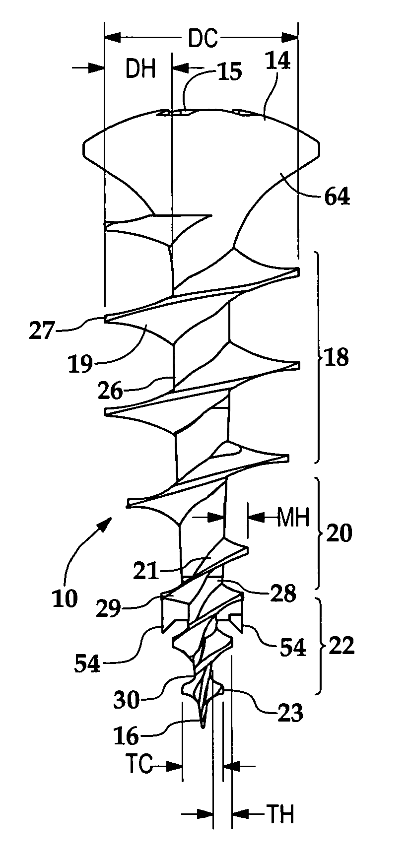
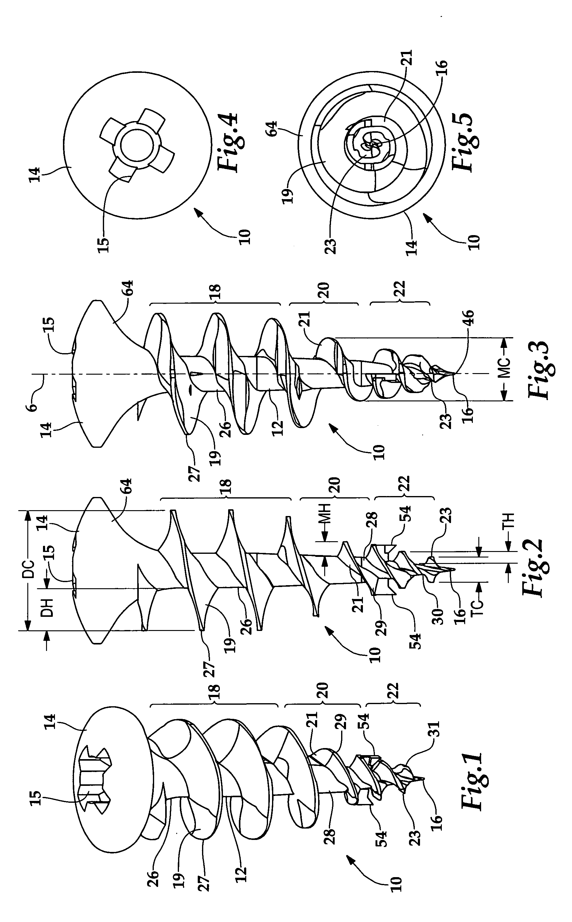
[0021] Referring to FIGS. 1-5, a novel self-drilling drywall fastener 10 is shown. Here, drywall fastener 10 is described in its general aspects and then, below, with respect to several exemplary embodiments, including the break-off tip embodiment shown in FIGS. 1-5.

[0022] Drywall fastener 10 is for use in a friable material, such as drywall, mounted on a member, such as a support member or stud, the novel drywall fastener 10 having an elongated body 12 with an axis 6, an enlarged head 14 having torque transmitting surfaces 15 therein, a proximal portion 18 proximate enlarged head 14, an intermediate portion 20, a distal portion 22, and a drilling tip 16 generally opposite enlarged head 14, wherein proximal portion 18 has a threaded exterior, such as drywall gripping threading 19, having a root 26, a crest 27 with a crest diameter DC, and a thread height DH, intermediate portion 20 has a threaded exterior, such as member gripping threading 21, having a root 28, a crest 29 with a cr...


PUM


Abstract

A self drilling fastener for use in a friable material mounted on a member comprises an elongated body having an axis, an enlarged head having torque transmitting surfaces therein, a proximal portion, an intermediate portion, a distal portion, and a drilling tip generally opposite the enlarged head. The proximal portion has a threaded exterior having a root, a crest diameter, and a thread height. The intermediate portion has a threaded exterior having a root, a crest diameter substantially smaller than the crest diameter of the proximal portion, and a thread height substantially smaller than the thread height of the proximal portion. The distal portion has a threaded exterior with a root that tapers toward the drilling tip, a crest diameter substantially smaller than the crest diameter of the proximal portion, and a thread height substantially smaller than the thread height of the proximal portion.

Description

[0001] This application is a continuation-in-part of U.S. patent application Ser. No. 10 / 939,795, filed on Sep. 13, 2004, and of U.S. patent application Ser. No. 10 / 844,706, filed on May 12, 2004, which claims priority to U.S. Provisional Application No. 60 / 510,708, filed on Oct. 10, 2003.BACKGROUND OF THE INVENTION [0002] 1. Field of the Invention [0003] The present invention is directed to a drywall fastener for use in a friable material, including a self-drilling drywall fastener to be used in drywall mounted to a stud member or the like. [0004] 2. Description of the Related Art [0005] Because drywall is a friable material, mounting articles thereto can be difficult. In the past, at least three methods have been used. For light weight articles, small plastic expansion anchors have been used. These expansion anchors have typically required three steps to install: first, a hole is drilled into the drywall; second, the drywall fastener insert is driven into the drilled hole; and fin...

Claims


Application Information

Patent Timeline
IPC IPC(8): F16B13/04
CPCF16B13/002F16B25/10F16B25/0057F16B25/0031
Inventor ERNST, RICHARD J.
Owner ILLINOIS TOOL WORKS INC
Learn More