Retractable intravenous tube organizer

a technology of intravenous tubes and organizers, which is applied in the field of medical devices, can solve the problems of unsafe patient care, time-consuming for nurses to unravel, and none of the previous devices are capable of solving the multitude of problems, etc., and achieves the effects of reducing the risk of patients, reducing the risk of complications, and reducing the safety of patients

a technology of intravenous tubes and organizers, which is applied in the field of medical devices, can solve the problems of unsafe patient care, time-consuming for nurses to unravel, and none of the previous devices are capable of solving the multitude of problems, etc., and achieves the effects of reducing the risk of patients, reducing the risk of complications, and reducing the safety of patients

US20060020257A1Inactive Publication Date: 2006-01-26MAMBOURG JOSEPH ROLLAND

Image

  • Retractable intravenous tube organizer
  • Retractable intravenous tube organizer
  • Retractable intravenous tube organizer

Examples


Embodiment Construction

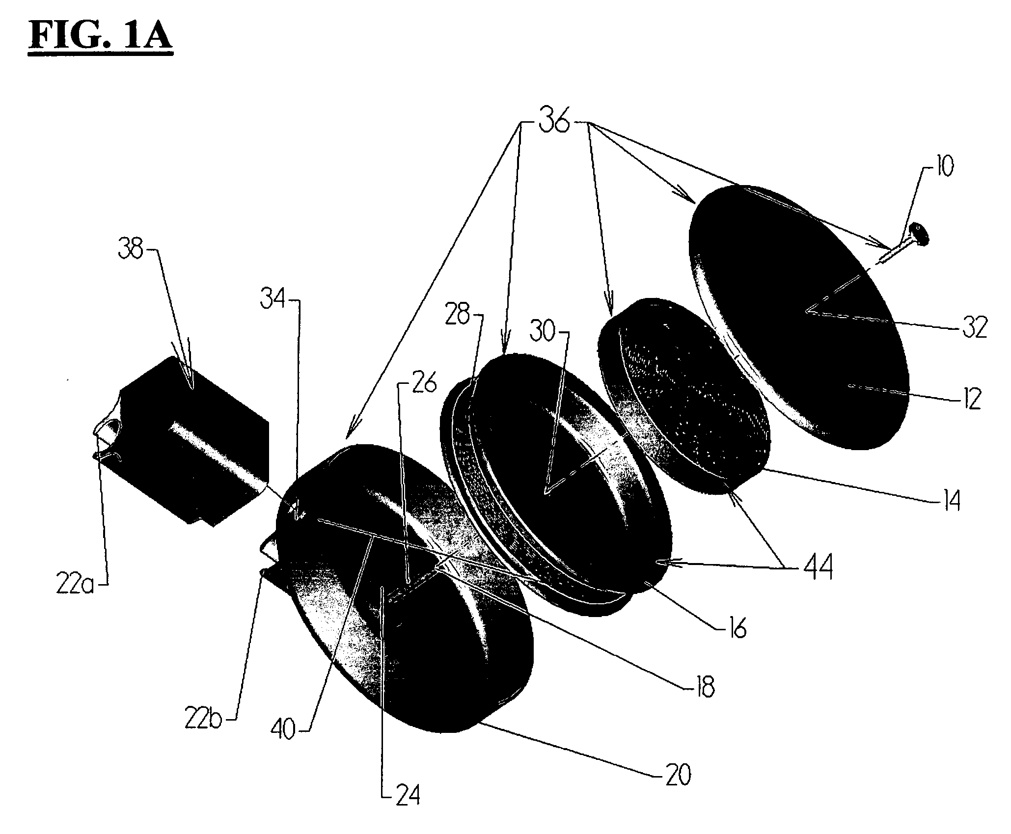
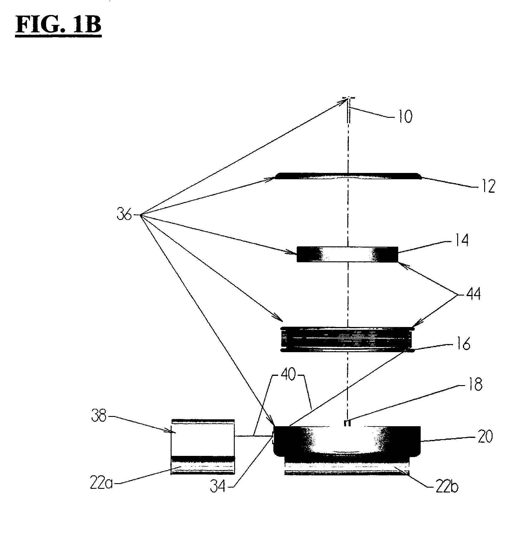
—FIGS. 1A, 1B AND 1C—PREFERRED EMBODIMENT

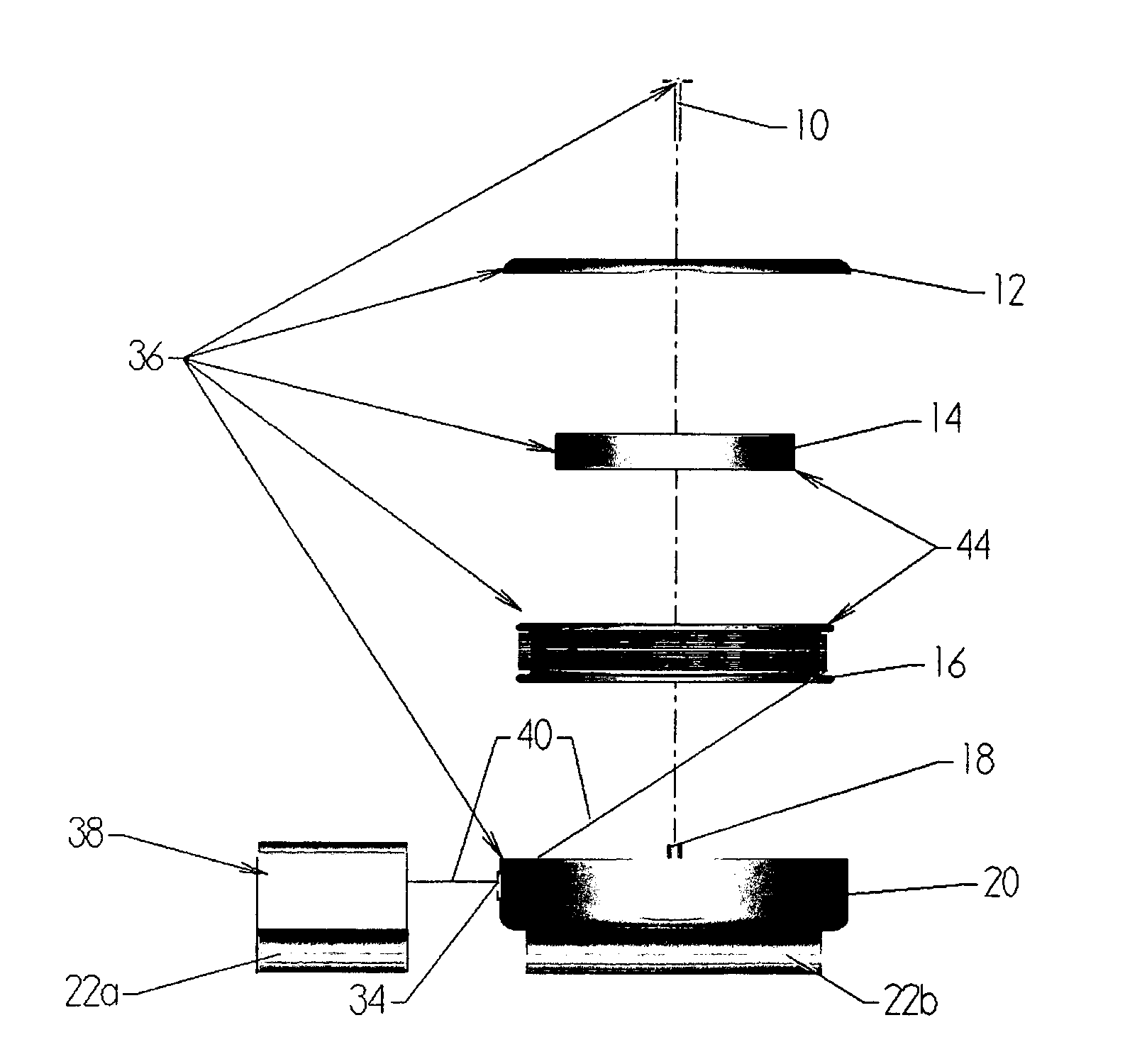
[0030] A preferred embodiment of the present invention is illustrated in FIG. 1A (expanded isometric view), FIG. 1B (expanded side view) and FIG. 1C (expanded top view). The present invention has a base assembly 36 consisting of a base clip 22b, a base top 20, a cord holder rest 24, an axle 18, a retracting mechanism assembly 44, a base bottom 12, and an attachment screw 10. The retracting mechanism assembly 44 consists of a cord holder 16 and a retract spring 14. The retract base assembly 38 consists of a retract clip 22a and a hole 42. (FIGS. 3A and 3B.)

[0031] In the preferred embodiment of the retracting mechanism assembly 44, the retract spring 14 rests inside the cord holder 16 and is attached to the cord holder at the spring attachment point 28.

[0032] In the preferred embodiment of the base assembly 36, the axle 18 is inserted through hole 30 until the retracting mechanism assembly 44 rests on the cord holder rest 24. The retract spri...


PUM


Abstract

An intravenous tube organizer for use in hospitals. The present invention consists of a base and a retract base. The base contains a retracting mechanism as a means for retracting and extracting the retract base from the base. The base is attached to the retract base via the retracting mechanism and a cord. Both the base and retract base have an exterior clip that is designed to attach the intravenous tube to the respective bases without the crimping or tearing of the intravenous tube. The ultimate advantage of this device is that it allows for safe organization of intravenous tubes while still allowing the patients full mobility.

Description

CROSS-REFERENCE TO RELATED APPLICATIONS [0001] Not Applicable FEDERALLY SPONSORED RESEARCH [0002] Not Applicable SEQUENCE LISTING OR PROGRAM [0003] Not Applicable BACKGROUND OF THE INVENTION [0004] 1. Field of Invention [0005] This invention relates to medical instruments, specifically to a device that organizes an intravenous tube. [0006] 2. Discussion of Prior Art [0007] Everyday, hospital patients around the world wake up to a continued fight for their own survival. Modern medicine, with its many technologies and methods, tries to help these individuals as much as possible with the continuous infusion of medicines and other fluids. These injections are usually administered into the patient's body through tubes called Intravenous lines. These Intravenous (I.V.) lines allow the medicine to be injected directly into the blood stream without the need for constant injections. Unfortunately, these lines can only carry one medicine at a time; thus, as many as ten different I.V. lines ca...

Claims


Application Information

Patent Timeline
26 Jan 2006
Publication
US20060020257A1
IPC
A61B17/00
CPC
A61M39/08; A61M5/1418
Inventors
MAMBOURG, JOSEPH ROLLAND