System and method for interleaving data in a communication device

a communication device and data technology, applied in the field of communication networks, can solve the problems of introducing errors into packets of information transmitted over the system, random bursts of noise, burst noise or impulse noise, etc., and achieve the effect of optimal throughput and efficiency of the system and minimizing unnecessary delays

Inactive Publication Date: 2006-02-02
AVAGO TECH INT SALES PTE LTD
View PDF8 Cites 90 Cited by
  • Summary
  • Abstract
  • Description
  • Claims
  • Application Information

AI Technical Summary

Benefits of technology

[0017] A system in accordance with embodiments of the present invention further includes a block available signal for indicating to the read module when a block of data is available for reading and a block out signal for indicating to the write module that a block of data has been read from the memory. The read module also maintains a clear read pointer for preventing the write module from overwriting unread data in the memory. The above-described signals enable the write module to continuously write as many blocks into the memory as can be accommodated therein and enable the read module to continuously read as many blocks of data as are available in the memory. Thus, unnecessary delays are minimized in systems where the block size of the data is variable. As a result, optimal throughput and efficiency of the system is realized.

Problems solved by technology

As in other communications systems, cable modem systems may be subject to intermittent, random bursts of noise, often referred to as burst noise or impulse noise.
When such a noise burst occurs, it may introduce errors into packets of information transmitted over the system.
Thus, three data errors in the data will remain.
However, the above-described system may incur processing delays in a system where blocks may be of a variable size.

Method used


Image

  • System and method for interleaving data in a communication device
  • System and method for interleaving data in a communication device
  • System and method for interleaving data in a communication device

Examples


Embodiment Construction

[0031] While the present invention is described herein with reference to a cable modem system, it should be understood that the invention is not limited thereto. Those skilled in the art with access to the teachings provided herein will recognize that embodiments of the present invention may be practiced in a wide variety of communication systems. For example, embodiments of the present invention may be implemented in any communication system in which electronic information is transmitted in packets.

A. System for Interleaving Data in Accordance with Embodiments of the Present Invention

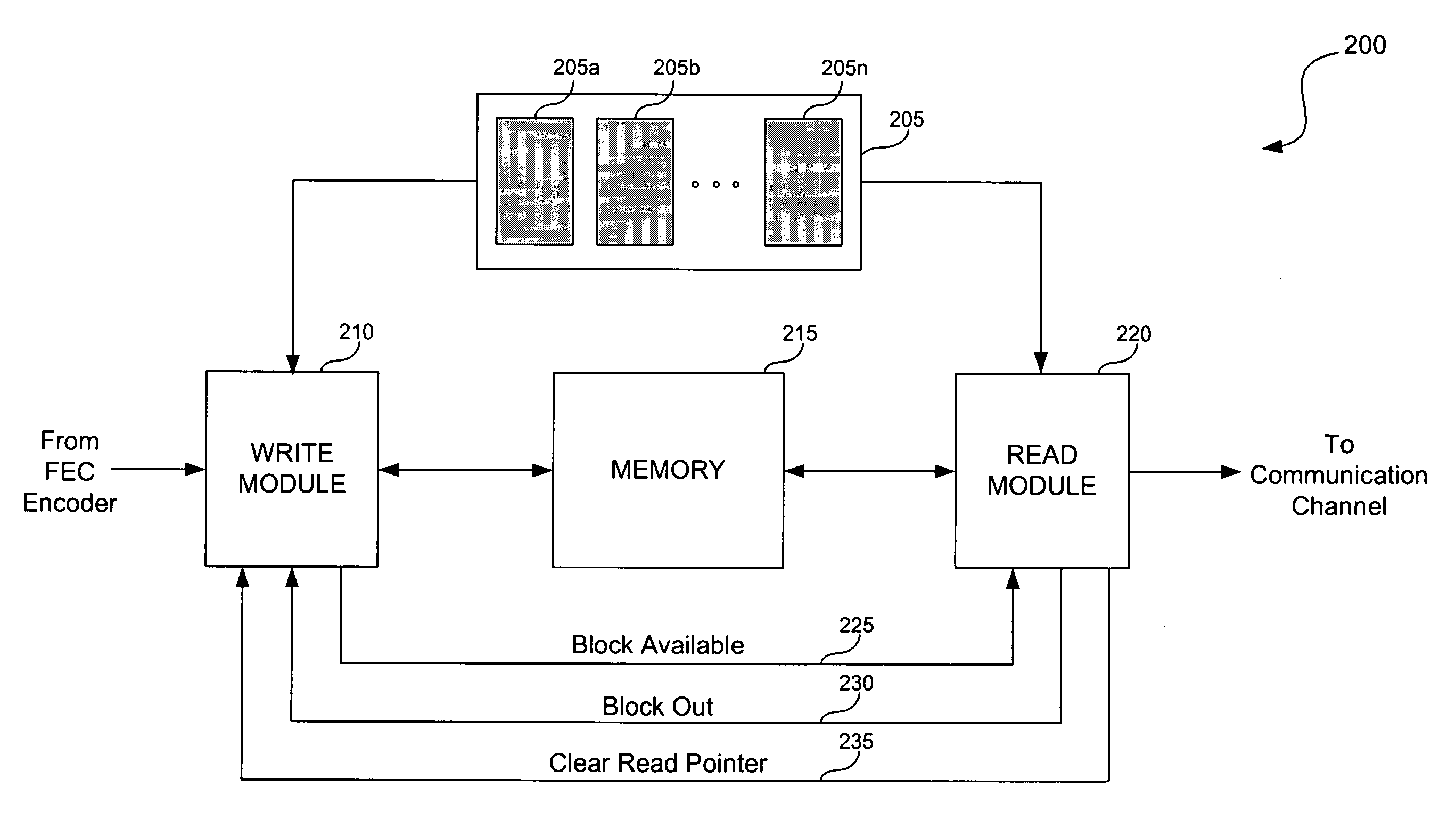
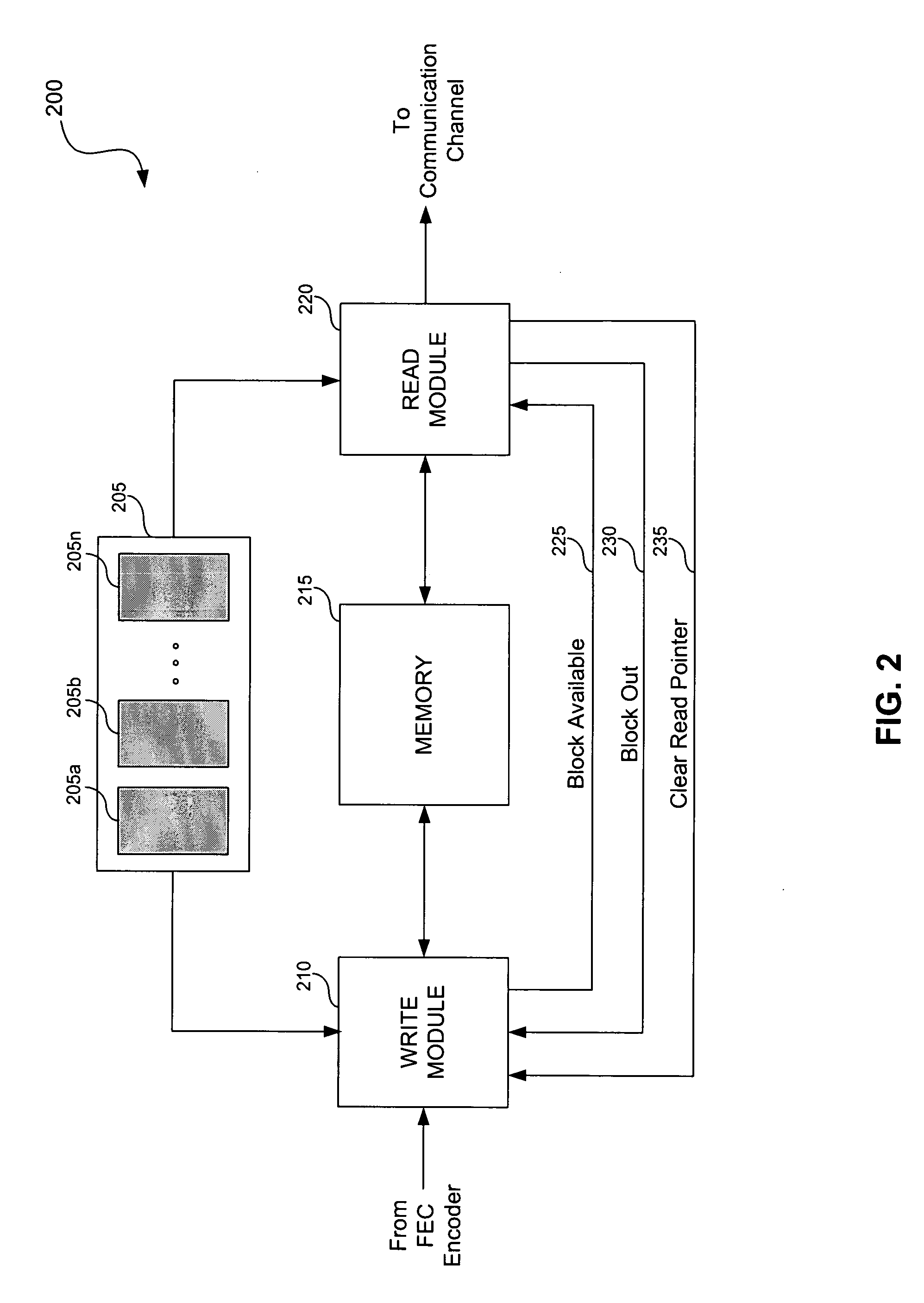
[0032]FIG. 2 illustrates a system for interleaving data in accordance with an embodiment of the present invention. FIG. 2 will be used to describe the structure and operation of system 200. Subsequent figures will describe timing and a greater level of detail of operation of system 200. System 200 may be implemented in the transmitter portion of a cable modem, a cable modem termination system (CMTS)...


PUM


Abstract

A system and method is provided for interleaving data in a communication device. The system includes a memory that stores blocks of data to be interleaved. In addition to the memory, the system includes a write module and a read module, each of which is coupled to the memory. The write module is configured to receive a burst of data and write blocks of data from the burst into the memory. The write module is also configured to provide control information to the read logic. The control information includes a rolling burst counter and a burst profile bank identifier for each block. If interleaving is activated, the control information also includes information pertaining to how the read module should interleave the block. If interleaving is not activated, the control information also includes the byte length size of the burst. The read module reads blocks of data from memory in either an interleaved fashion or a non-interleaved fashion in accordance with the control information. A block available signal and a block out signal is also provided to determine when a block of data is available to be read from the memory.

Description

CROSS REFERENCE TO RELATED APPLICATIONS [0001] This application claims priority to provisional U.S. application Ser. No. 60 / 296,452, entitled “System and Method for Writing Data in an Interleaver RAM,” filed Jun. 8, 2001, which is incorporated by reference in its entirety as if set forth fully herein.BACKGROUND OF THE INVENTION [0002] 1. Field of the Invention [0003] The present invention is generally related to communication networks. More particularly, the present invention is related to systems and methods for interleaving data in communication devices. [0004] 2. Related Art [0005] As in other communications systems, cable modem systems may be subject to intermittent, random bursts of noise, often referred to as burst noise or impulse noise. When such a noise burst occurs, it may introduce errors into packets of information transmitted over the system. In some cases, these errors may be corrected by Forward Error Correction (FEC). The ability of FEC to correct errors may be furth...

Claims


Application Information

Patent Timeline
Patent Type & Authority Applications(United States)
IPC IPC(8): G06F11/00G06F11/30G08C25/00H03M13/00H04L1/00H03M13/27
CPCG06F11/1008G06F11/1076H03M13/2707H03M13/2785H04L2001/0094H04L1/0043H04L1/0057H04L1/0071H04L1/0075H03M13/2789
Inventor HOLLUMS, SCOTT
Owner AVAGO TECH INT SALES PTE LTD
Why Eureka
Try Eureka