Variable roller blind structure

a roller blind and variable technology, applied in the direction of curtain suspension devices, sliding/moving grilles, door/window protection devices, etc., can solve the problems of inability to variably operate the blind body, limited practical use, and monotonous conventional roller blinds, etc., to achieve efficient boosting the function

Inactive Publication Date: 2006-02-09
CHING FENG BLINDS INC CO LTD
View PDF5 Cites 46 Cited by
  • Summary
  • Abstract
  • Description
  • Claims
  • Application Information

AI Technical Summary

Benefits of technology

[0003] It is, therefore, the primary purpose of the present invention to provide a variable roller blind structure, including a roller blind made up of more than one blind bodies that are juxtaposed at an interval wherein each blind body has a plurality of light-passable areas alternatively arranged with a plurality of black-out areas disposed at the surface thereon so that the roller blind can be operated to have it both ways with partial transparency and partial sheltering function for privacy purpose. Besides, when a rotatable roller shaft is wound by an operating member to actuate the rolling movement of one blind body till the light-passable areas of the blind body are correspondingly aligned with the black-out areas of the other blind body, the light-passable areas of each blind body thereof can be precisely sheltered by the black-out areas of the other respectively, completely blocking out all light outdoors so as to achieve a universal sheltering effect thereof. Thus, the roller blind thereof can be variably operated to cater to the needs of users, efficiently boosting its functions to provide a user-oriented design so as to achieve the best using condition thereof.

Problems solved by technology

In practical use, the blind body is unable to be variably operated to have it both ways with partial transparency and partial sheltering function or to have a completely block-out of light and view outsides.
Thus, the conventional roller blind is rather monotonously made and quite limited in practical use thereof

Method used


Image

  • Variable roller blind structure
  • Variable roller blind structure
  • Variable roller blind structure

Examples


Embodiment Construction

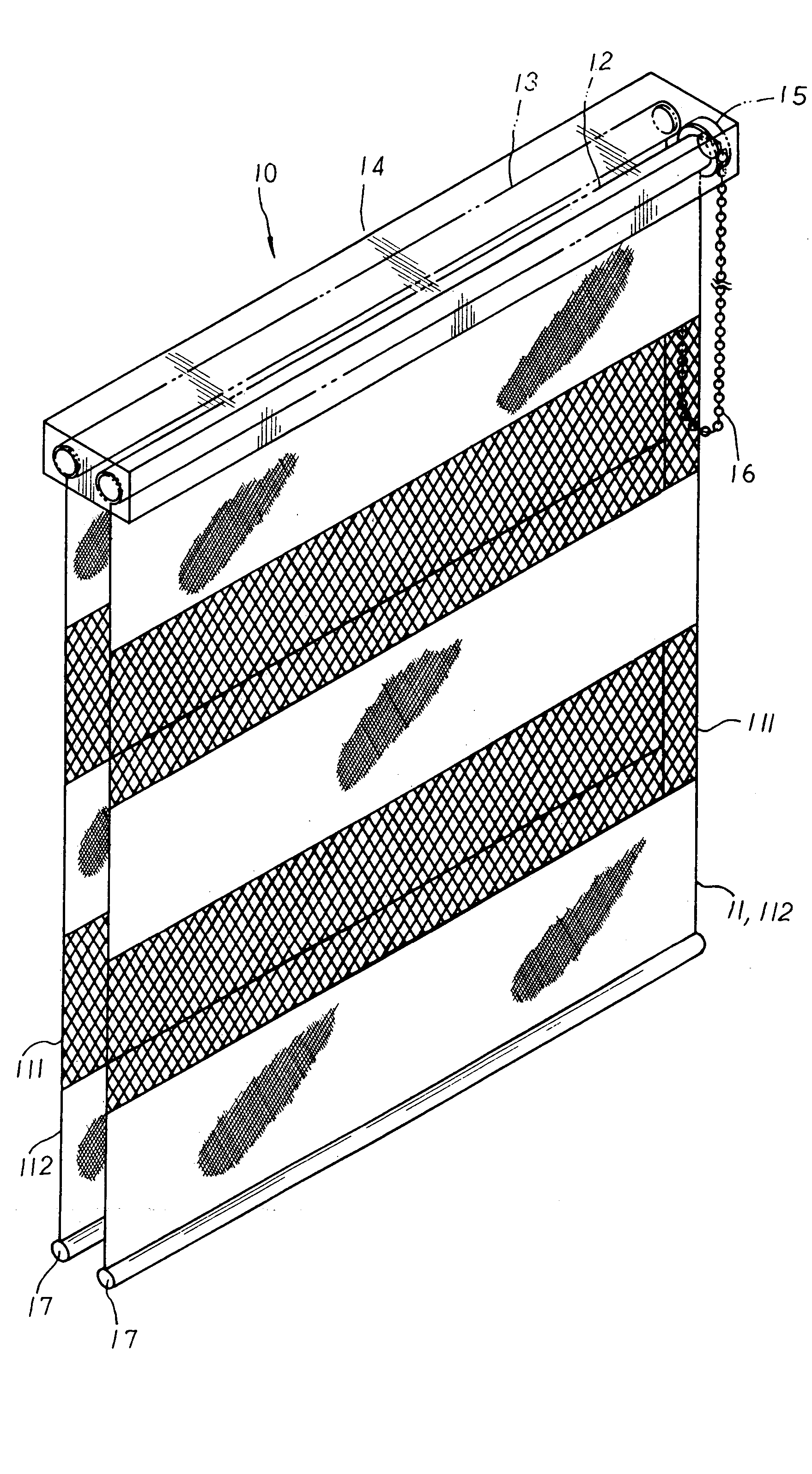
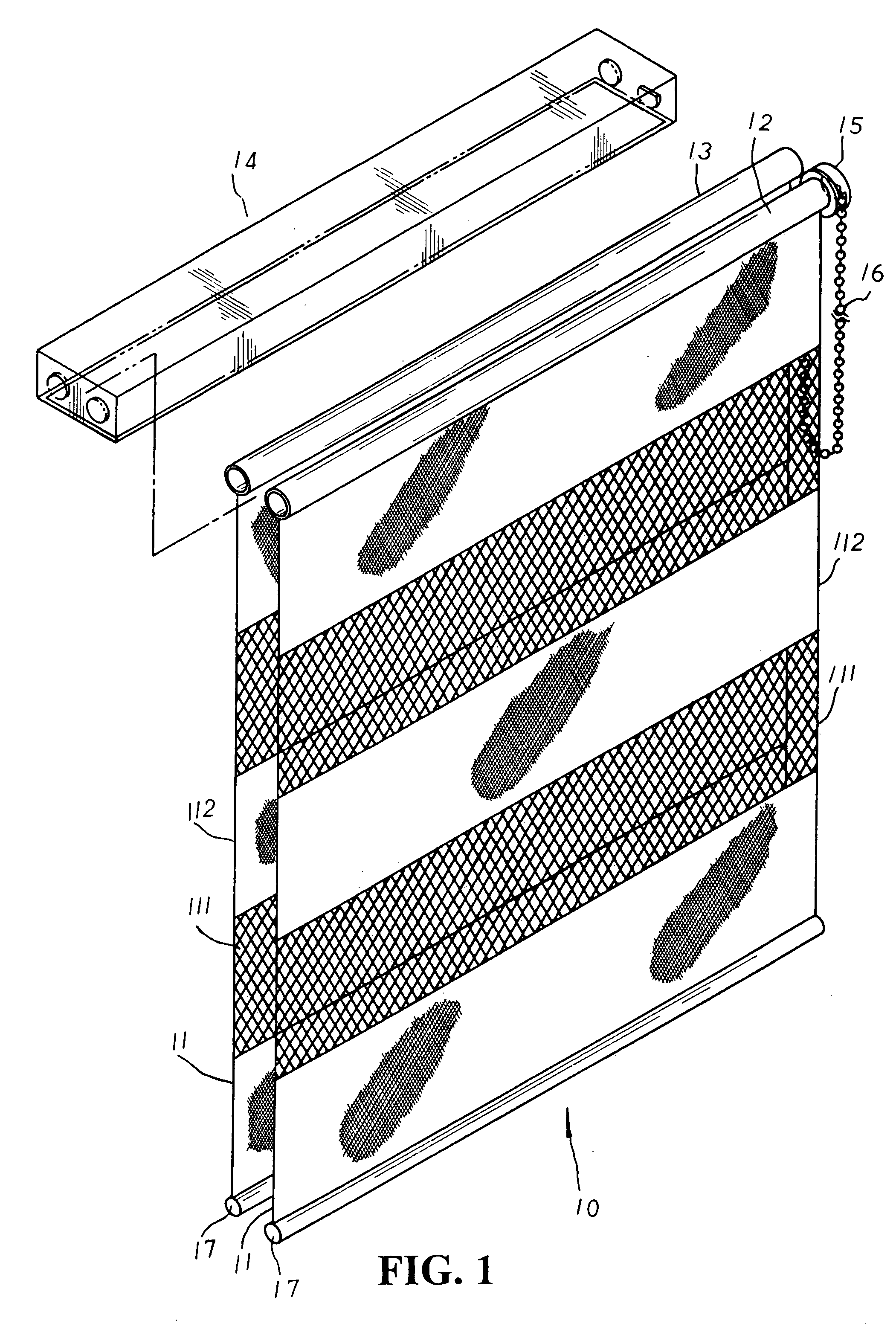
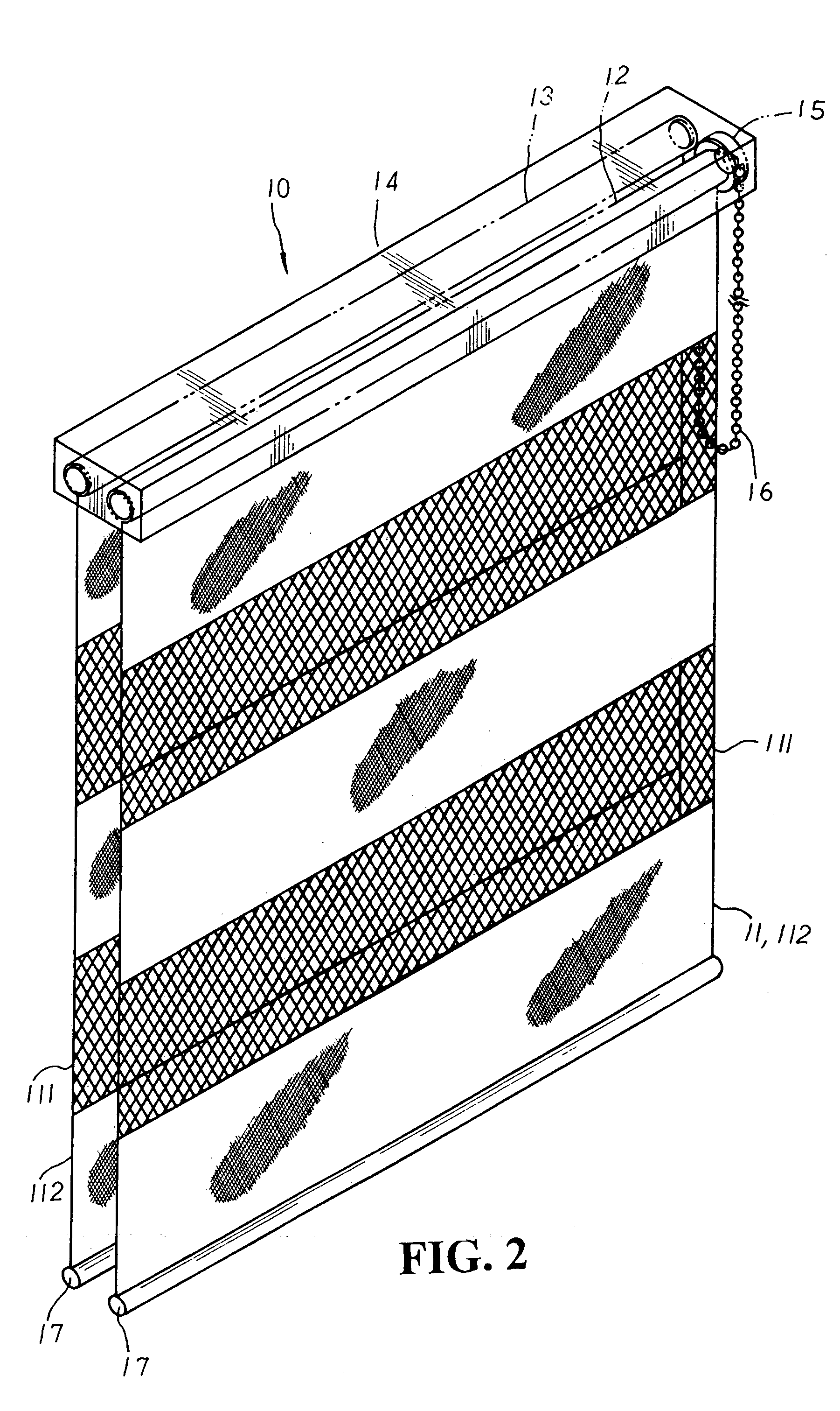
[0015] Please refer to FIGS. 1 to 3 inclusive. The present invention is related to a variable roller blind structure, including a roller blind 10 made up of more than one blind bodies 11 each equipped with a plurality of light-passable areas 111 alternatively arranged with a plurality of black-out areas 112 disposed at the surface thereon. The light-passable areas 111 of the blind body 11 can be made in net-like or porous shape, and the height of each black-out area 11.2 is slightly higher than that of the light-passable areas 111 thereof. At the top edge of the blind bodies 11 are respectively attached a rotatable roller shaft 12 and a stable roller shaft 13 that are juxtaposed at an interval and mounted at the inner side of an upper beam 14 therein. A manual-operated winding unit 15 or an automatic winding unit 15′ with a spring element 151′ attached thereto as shown in FIG. 3 is mutually engaged with the rotatable roller shaft 12 thereof to be actuated by an operating member 16 s...


PUM


Abstract

A variable roller blind structure includes a roller blind made up of more than one blind bodies that are respectively attached to the underside of a rotatable roller shaft and a stable roller shaft juxtaposed at an interval and mounted at the inner side of an upper beam. The blind body has a plurality of light-passable areas alternatively arranged with a plurality of black-out areas disposed at the surface thereon, and a winding unit is mutually engaged with the rotatable roller shaft to be controlled by an operating member that is pulled either clockwise or counterclockwise to actuate the movement of the rotatable roller shaft accordingly so as to control the rolling or unrolling operation of the blind body thereby. Via the structure above, the blind bodies of the roller blind can have it both ways with partial transparency and partial sheltering effect for privacy purpose. Besides, when the rotatable roller shaft is wound by the operating member to actuate the rolling movement the blind body till the light-passable areas of the blind body rolled upwards are correspondingly juxtaposed with the black-out areas of the other blind body, the light-passable areas of each blind body thereof can be precisely sheltered by the black-out areas of the other respectively, completely blocking out all light outdoors so as to achieve a total sheltering effect thereof. Thus, the roller blind thereof is capable of being variably operated to cater to the needs of users and is efficiently boosted in its functions thereof.

Description

BACKGROUND OF THE INVENTION [0001] The present invention is related to a variable roller blind structure, including a roller blind made up of more than one blind bodies that are juxtaposed at an interval wherein each blind body has a plurality of light-passable areas alternatively arranged with a plurality of black-out areas disposed at the surface thereon so that the roller blind can be properly operated to have it both ways with partial transparency and partial sheltering function for privacy purpose. Besides, when a rotatable roller shaft is wound by an operating member to actuate the rolling movement of one blind body till the light-passable areas of the blind body are correspondingly aligned with the black-out areas of the other blind body, the light-passable areas of each blind body thereof can be precisely sheltered by the black-out areas of the other respectively, completely blocking out all light outdoors so as to achieve a total sheltering effect thereof. Thus, the roller ...

Claims


Application Information

Patent Timeline
Patent Type & Authority Applications(United States)
IPC IPC(8): A47H1/00A47H23/00E06B9/40
CPCE06B9/40E06B2009/2452E06B2009/2405
Inventor HSU, BEN
Owner CHING FENG BLINDS INC CO LTD
Why Eureka
Try Eureka