Graphical user interface system for a thermal comfort controller

a user interface and controller technology, applied in the field of thermal comfort controllers, can solve the problems of thermostats with limited user interfaces, save energy costs, and thermostats with setback capabilities, and achieve the effect of easy and intuitive programing and easy programming

Inactive Publication Date: 2006-02-09
ADEMCO INC
View PDF43 Cites 46 Cited by
  • Summary
  • Abstract
  • Description
  • Claims
  • Application Information

AI Technical Summary

Benefits of technology

This patent describes an improved user interface system for controlling heating and cooling systems that makes it easier to programming temperatures based on different needs during the day. The system uses a touch-screen display connected either to a wall-mounted thermostat or a portable device like a smartphone. It displays the current temperature and helps users adjust their settings by showing them what they should aim to achieve. Users can change the temperature schedule over time or have several schedules running simultaneously. Overall, this new system provides better guidance and flexibility for managing hot and cold weather.

Problems solved by technology

The technical problem addressed in this patent is the limitations of current thermostats, including their difficult user interface and lack of ability to provide a visual representation of the temperature schedule being programmed. Users struggle to effectively use the settings saved on the thermostat, resulting in missed opportunities for energy savings. A better user experience is required to make it easier for consumers to manage their heating and cooling needs through efficient programming of the thermostat.

Method used


Image

  • Graphical user interface system for a thermal comfort controller
  • Graphical user interface system for a thermal comfort controller
  • Graphical user interface system for a thermal comfort controller

Examples


Embodiment Construction

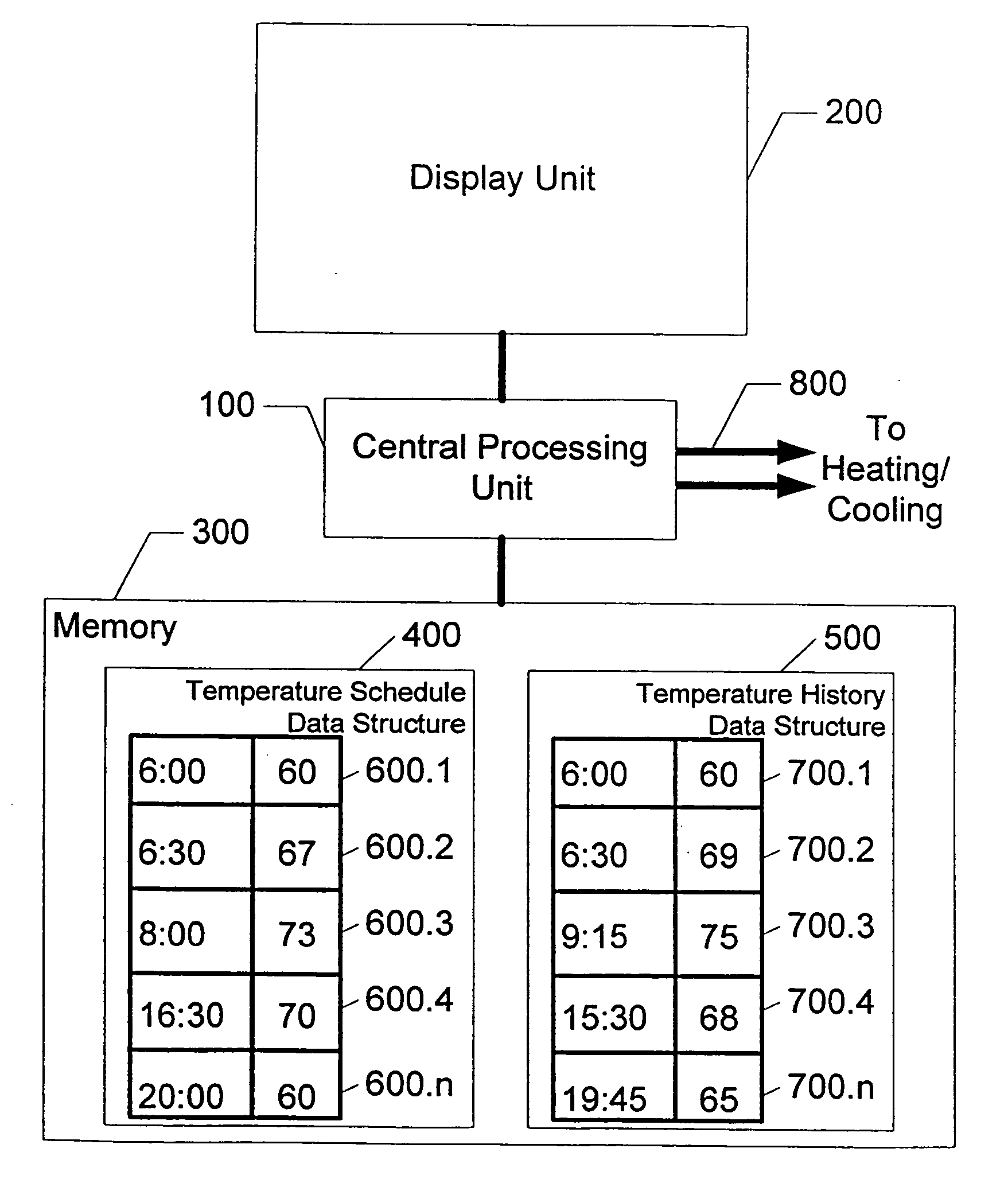
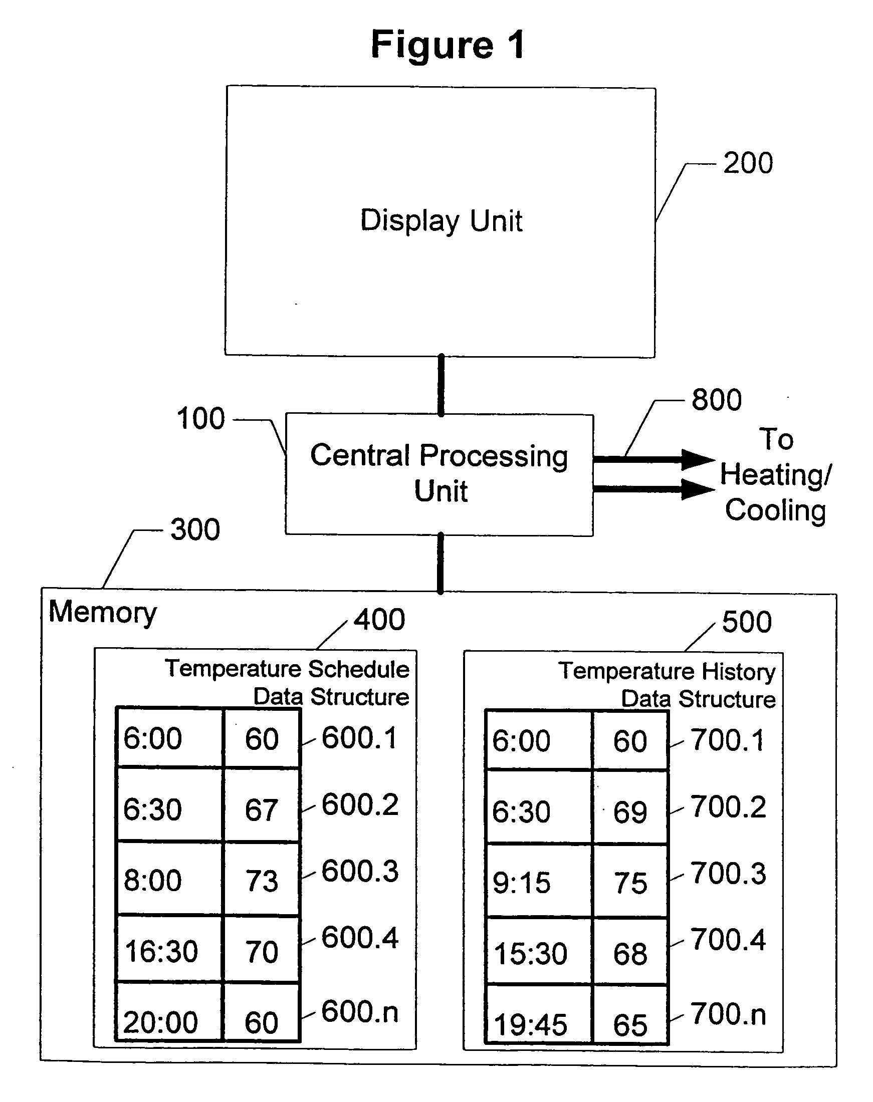
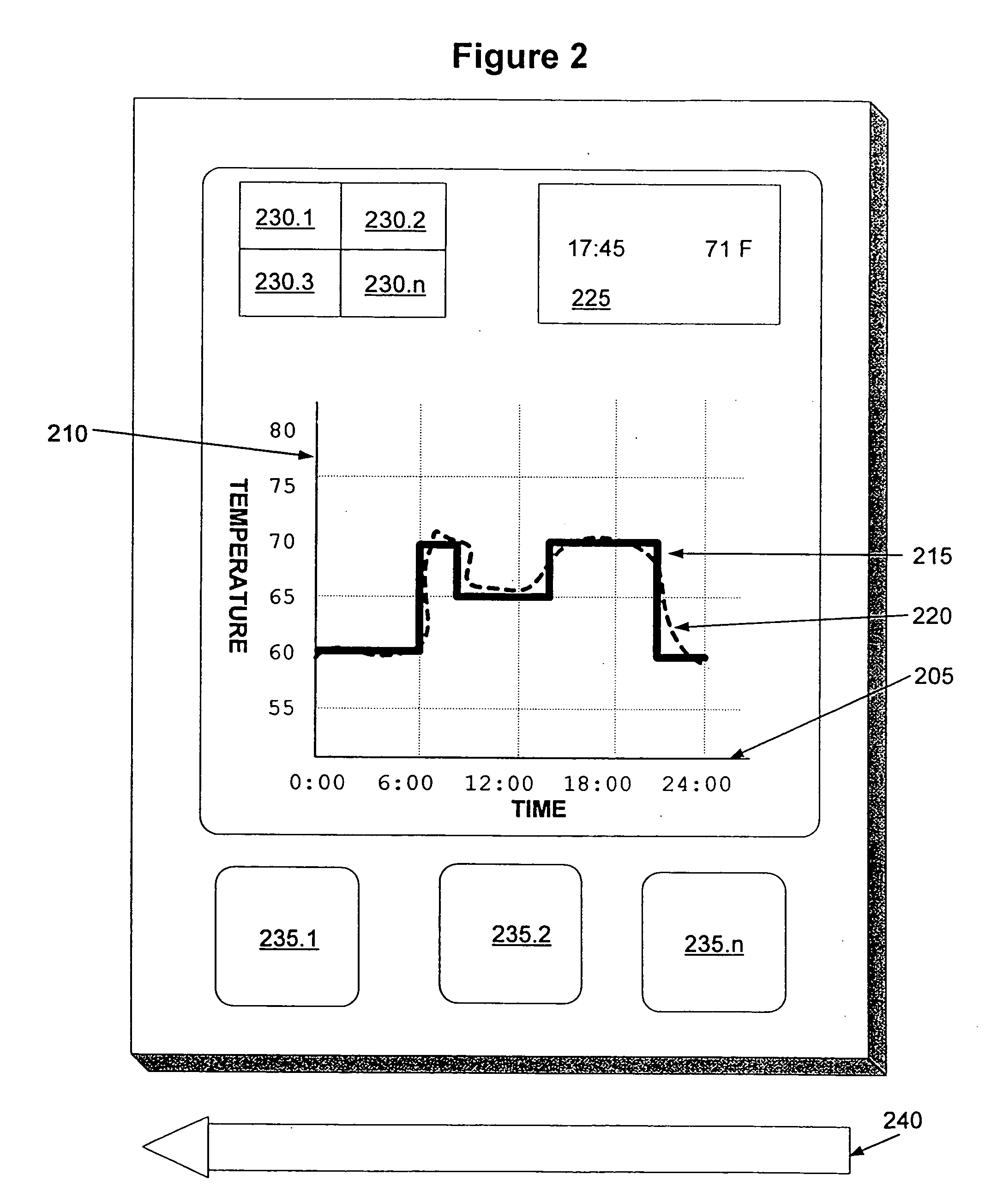
[0012] The present invention is a user interface system for a thermostat or other comfort controller. Throughout the drawings, an attempt has been made to label corresponding elements with the same reference numbers. The reference numbers include:

ReferenceNumberDescription100Central Processing Unit200Display Unit205Axis denoting Time210Axis denoting Temperature215Graphical Representation of Temperature Schedule220Graphical Representation of Temperature History225Other Data230Additional Controls235Buttons240Stylus300Memory400Temperature Schedule Data Structure500Temperature History Data Structure600Set-Point700Actual-Temperature-Point800Conduits to Heating / Cooling Devices or Thermostat

[0013] Referring to the drawings, FIG. 1 is a block diagram of the user interface system for a comfort controller. The user interface system includes a central processing unit 100. This central processing unit 100 is coupled to a display unit 200 and a memory 300. The display unit 200 has a torch-sens...


PUM


Abstract

A graphical user interface system for a thermal comfort controller. The user interface system has a central processing unit coupled to a memory and a touch sensitive display unit. The memory stores a temperature schedule data structure and perhaps a temperature history data structure. The temperature schedule data structure is made up of at least one set-point. The temperature history data structure is made up of at least one Actual-Temperature-Point. The display presents the set-points and/or the Actual-Temperature-Points. One representation of the display is a graphical step-function. The user uses a finger or stylus to program the set-points by pointing and dragging a portion of the step-function.

Description


Claims


Application Information

Patent Timeline
Owner ADEMCO INC
Why Eureka
Try Eureka