Vehicle bumper and method of making same

a technology for vehicles and bumpers, applied in the field of vehicles, can solve the problems of limited use of roll forming, impracticality of changing the cross-section, shape and design configuration of bumpers, and limiting the roll forming process, so as to achieve the effect of absorbing and dispersing energy

Inactive Publication Date: 2006-02-09
SKD AUTOMOTIVE GRP
View PDF31 Cites 58 Cited by
  • Summary
  • Abstract
  • Description
  • Claims
  • Application Information

AI Technical Summary

Benefits of technology

[0009] In accordance with a further embodiment, a plurality of deformation elements may be formed in the upper or lower walls of the respective first and second members to provide a path and / or area that deforms to absorb energy resulting from an impact load. Thus, the configuration of the inner and outer members, along with placement of deformation elements provides a vehicle bumper having a shape and structural design which helps to absorb and distribute energy resulting from a collision while being able to withstand a low impact collision without the need to repair or replace the bumper and other body parts, vehicle components or structure, as a result of a minor impact.

Problems solved by technology

Such a roll form process is limiting in that many of today's modern aerodynamic bumper shapes cannot be roll formed.
Further, it is impractical to change the cross-sections, shape and design configuration of the bumper over the length of the bumper.
Finally, roll forming is of limited use when forming many of the high strength steels used in today's bumper designs.

Method used


Image

  • Vehicle bumper and method of making same
  • Vehicle bumper and method of making same
  • Vehicle bumper and method of making same

Examples


Embodiment Construction

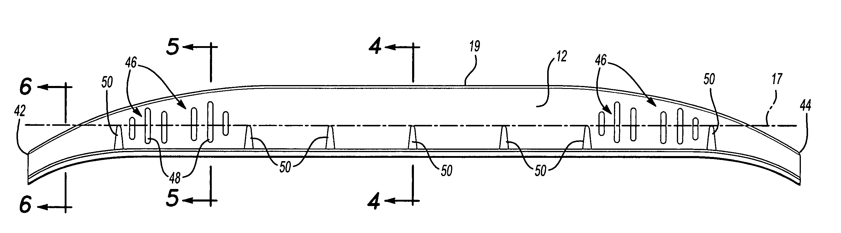
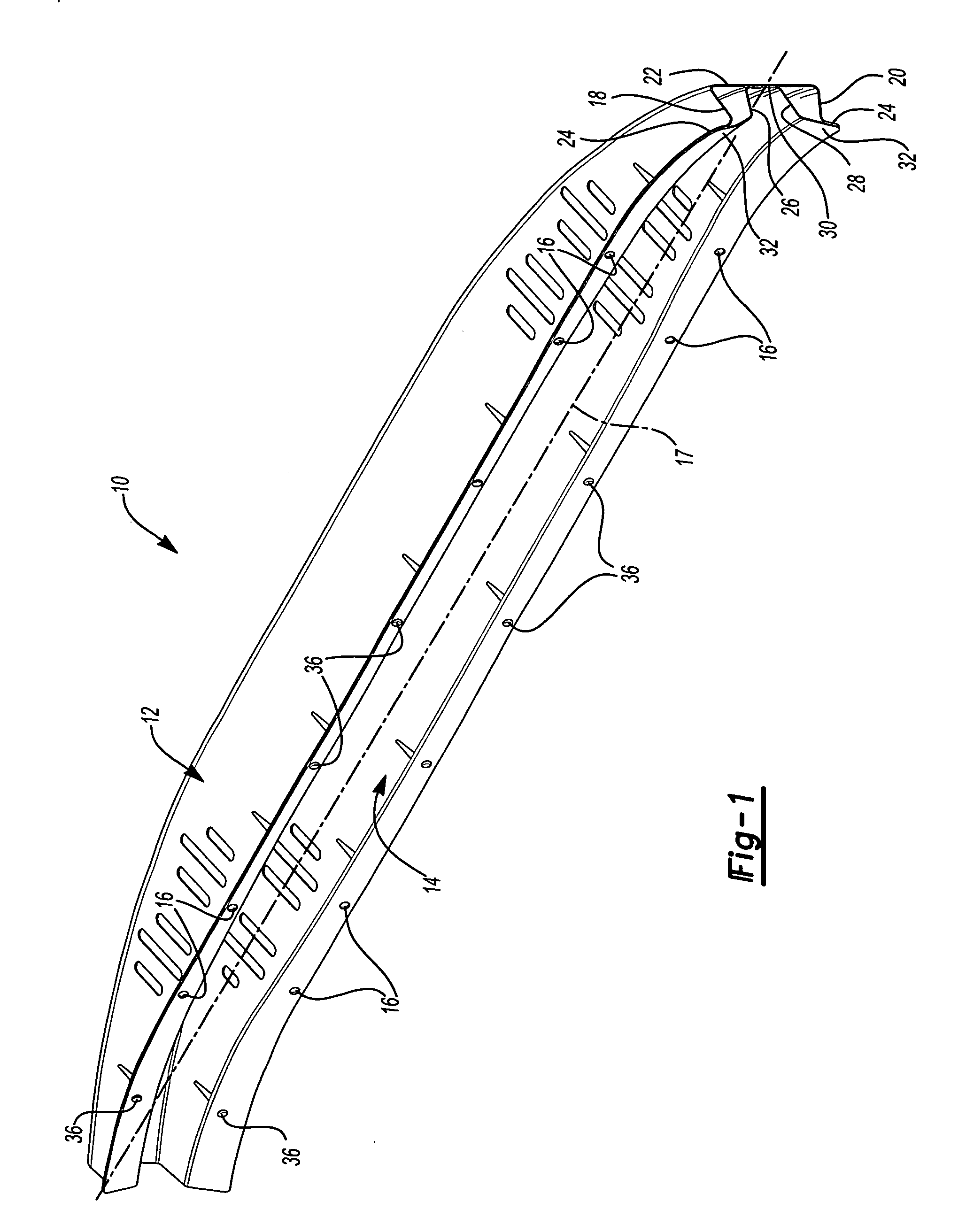
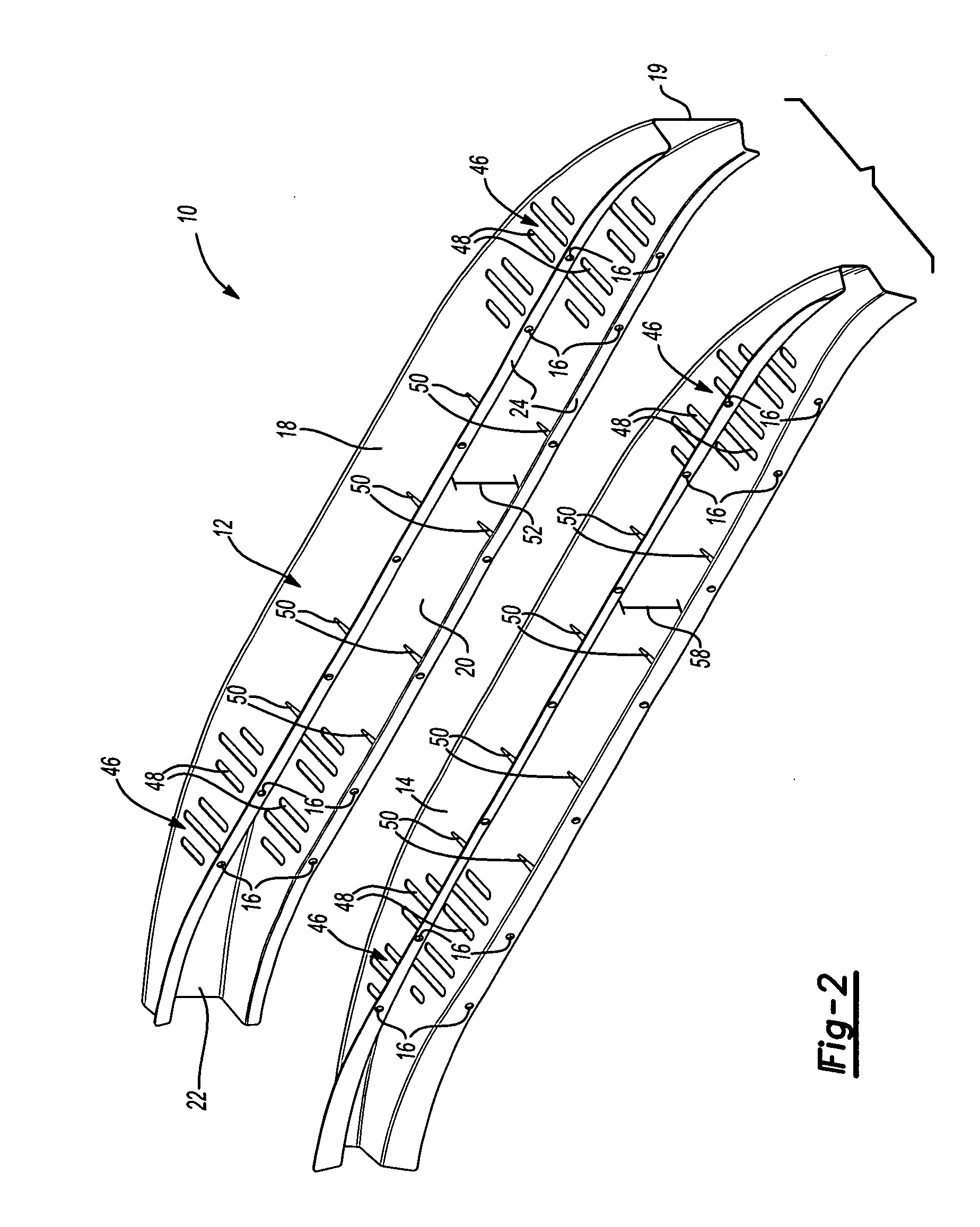
[0022]FIGS. 1 and 2 illustrate a vehicle bumper, seen generally at 10, according to one embodiment of the present invention. The vehicle bumper includes a first or outer member 12 and a second or inner member 14. As shown, the second or inner member 14 fits within the first or outer member 12 in a nested relationship. The vehicle bumper 10 includes a plurality of mounting holes 16 used to secure the bumper 10 to a vehicle frame (not shown.) In accordance with known mounting methods, other mounting plates, braces or supports may be used to secure the vehicle bumper 10 to the vehicle frame. In addition, it should be understood that a bumper cover (not shown) is typically secured to or placed over the vehicle bumper 10.

[0023] As shown in FIG. 1, the vehicle bumper 10 extends longitudinally along a longitudinal axis 17. In the present embodiment, the vehicle bumper 10 has a swept configuration. Swept is a term used in conjunction with vehicle bumpers to indicate the curvature of the bu...


PUM


Abstract

Accordingly, the present invention is a vehicle bumper and a method for making a vehicle bumper formed from first and second members wherein the second member is nested within the first member. Each of the first and second members has a front wall, an upper wall and a lower wall. Each member also includes flange portions extending outwardly from the respective upper and lower walls. The first and second members joined to one another at their respective front walls and flange portions. The first and second members formed in such a way that the cross-sections of the members varies along the longitudinal axis of the vehicle bumper. Varying the respective cross-sections enables a vehicle bumper design that helps to control energy transfer and absorption during a collision. In addition, it provides greater design and styling freedoms.

Description

BACKGROUND OF THE INVENTION [0001] 1. Field of the Invention [0002] The present invention relates generally to a vehicle bumper and, more particularly, to a bumper having inner and outer structural members combined to form the bumper. [0003] 2. Description of Related Art [0004] A bumper is attached typically to the front and rear end of a motor vehicle to absorb shock and to protect the passengers during a collision. The bumper is typically coupled to the vehicle frame and should be strong enough to withstand and absorb damage from a low impact collision. Being able to withstand a low impact collision reduces the need to repair or replace the bumper, along with other body parts, vehicle components or structure, as a result of a minor impact. [0005] In addition, the bumper should have a shape and structural design such that during a collision it helps to absorb and distribute the energy resulting from the collision and to transmit the energy to the vehicle frame. Modern vehicles trad...

Claims


Application Information

Patent Timeline
Patent Type & Authority Applications(United States)
IPC IPC(8): B60R19/04
CPCB60R2019/1826B60R19/18
Inventor HENSELEIT, KARL
Owner SKD AUTOMOTIVE GRP
Why Eureka
Try Eureka