

Structure of single fishing line guide for fishing rod
- Summary
- Abstract
- Description
- Claims
- Application Information
AI Technical Summary
Benefits of technology
Problems solved by technology
Method used
Image

Examples
Embodiment Construction
[0020] Now, preferred embodiments of the present invention will be described in detail with reference to the annexed drawings.
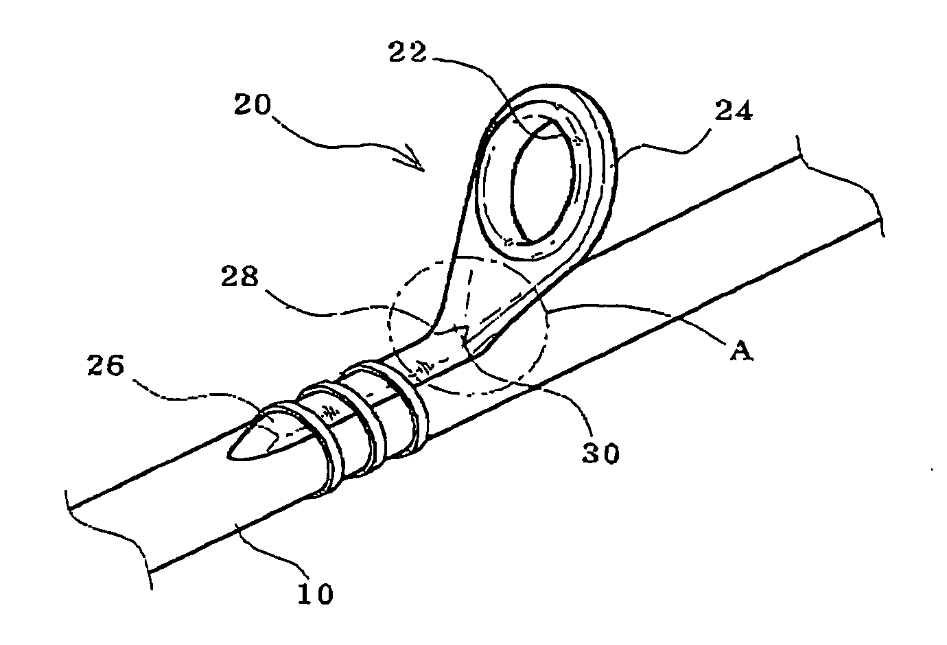
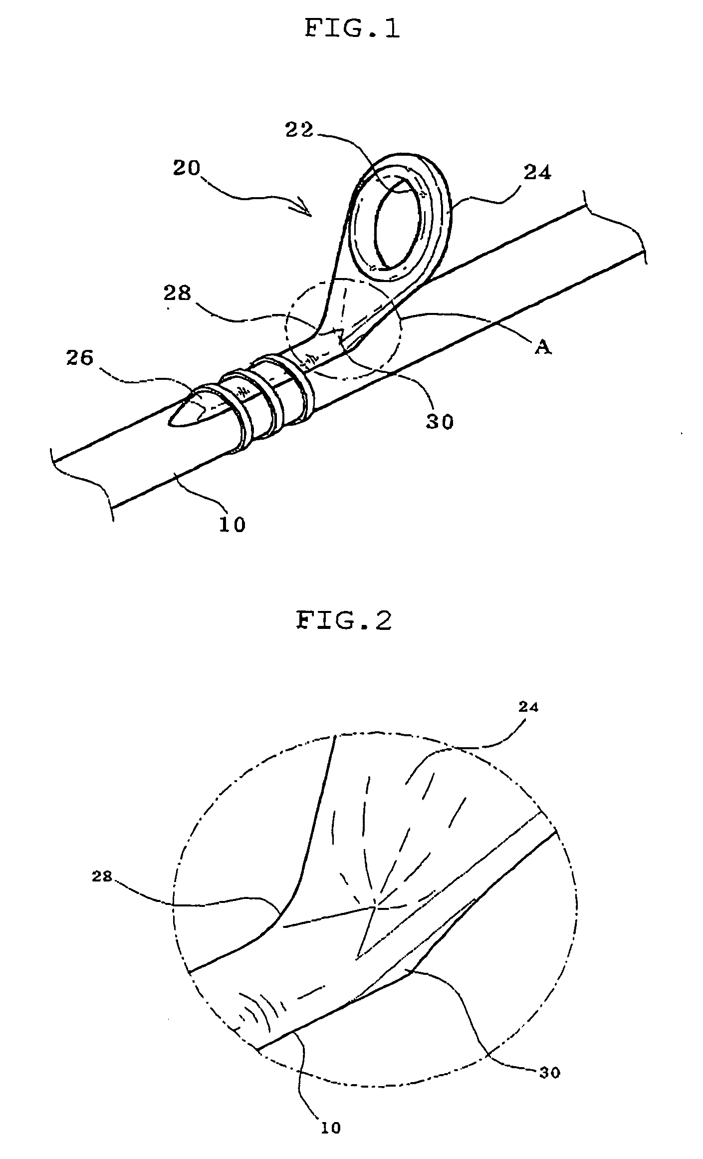
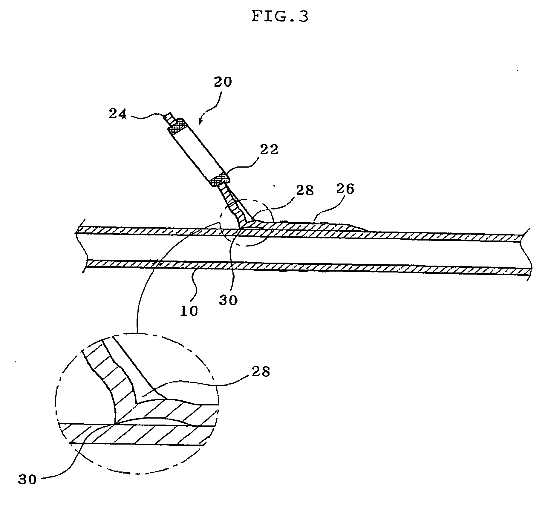
[0021]FIG. 1 is a perspective view illustrating the installation of a single fishing line guide for a fishing rod in accordance with one embodiment of the present invention. FIG. 2 is an enlarged view of the portion “A” of FIG. 1, and FIG. 3 is a cross-sectional view of the single fishing line guide of FIG. 1.
[0022]FIG. 4 is a perspective view illustrating the installation of a single fishing line guide for a fishing rod in accordance with another embodiment of the present invention. FIG. 5 is an enlarged view of the portion “B” of FIG. 4, and FIG. 6 is a cross-sectional view of the single fishing line guide of FIG. 4.
[0023] As shown in FIGS. 1 to 3, the fishing rod 10 has a plurality of fishing line guides 20 fixed thereto in the longitudinal direction.
[0024] Here, the fishing line guides 20 in accordance with one embodiment of the present invention deno...
PUM
 Abstract
Description
Claims
Application Information