UPS battery charger and UPS

A battery charger and electrolytic capacitor technology, applied in the field of UPS, can solve the problems of the influence of the input current index of the whole machine, the increase of the ripple current, and the increase of the cost of the whole machine, so as to improve the quality of the output current, stabilize the input voltage, and save costs Effect

Active Publication Date: 2010-03-24
VERTIV CORP
View PDF0 Cites 15 Cited by
  • Summary
  • Abstract
  • Description
  • Claims
  • Application Information

AI Technical Summary

Problems solved by technology

Usually the design power of these conversion devices is relatively small (generally below 500W). If the battery capacity is relatively large and requires a larger charger power (such as above 1KW), the most common method is to use two or more chargers. This kind of device is used in parallel to improve the charging capacity, but the most direct impact of this method is that the cost of the whole machine rises sharply
The fundamental reason is that this charger topology has no

Method used


Image

  • UPS battery charger and UPS
  • UPS battery charger and UPS

Examples


Embodiment 1

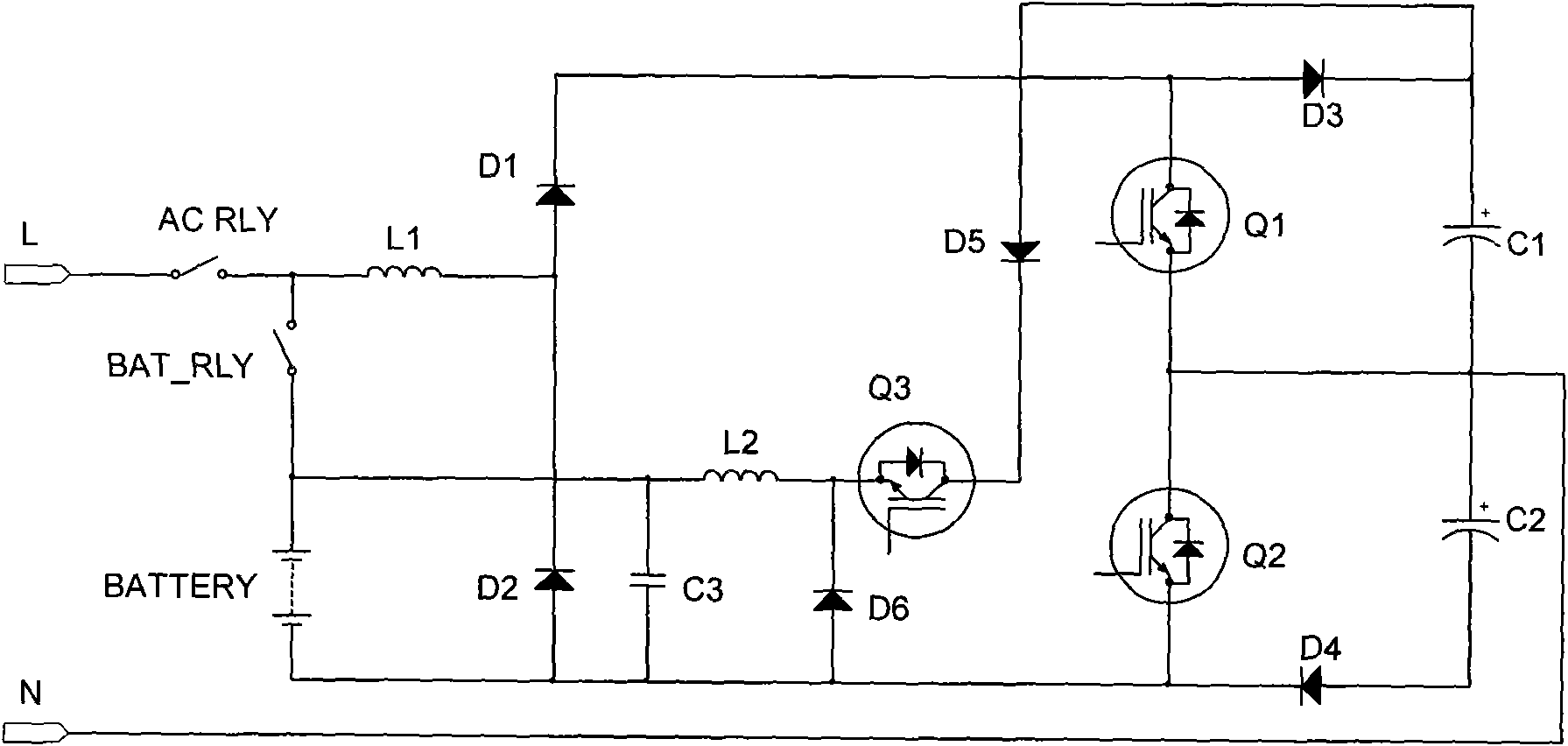
[0024] Please refer to figure 1 , the UPS battery charger includes a rectifier circuit, a PFC chopper circuit and a BUCK (step-down) converter. The output terminal of the wave circuit is coupled to the AC input zero line N through the positive and negative busbars, the input terminal of the BUCK converter is coupled to the positive busbar, and the output terminal of the BUCK converter is coupled to the positive and negative poles of the rechargeable battery BATTERY.

[0025] The rectifier circuit includes a first inductor L1, a first diode D1, and a second diode D2, and the PFC chopper circuit includes a third diode D3, a fourth diode D4, a first electrolytic capacitor C1, and a second electrolytic capacitor Capacitor C2 and the first switching tube Q1 and the second switching tube Q2 with anti-parallel diodes, one end of the first inductor L1 is coupled to the AC input live line L through the mains input switch AC_RLY, the other end of the first inductor L1 is connected to th...

Embodiment 2

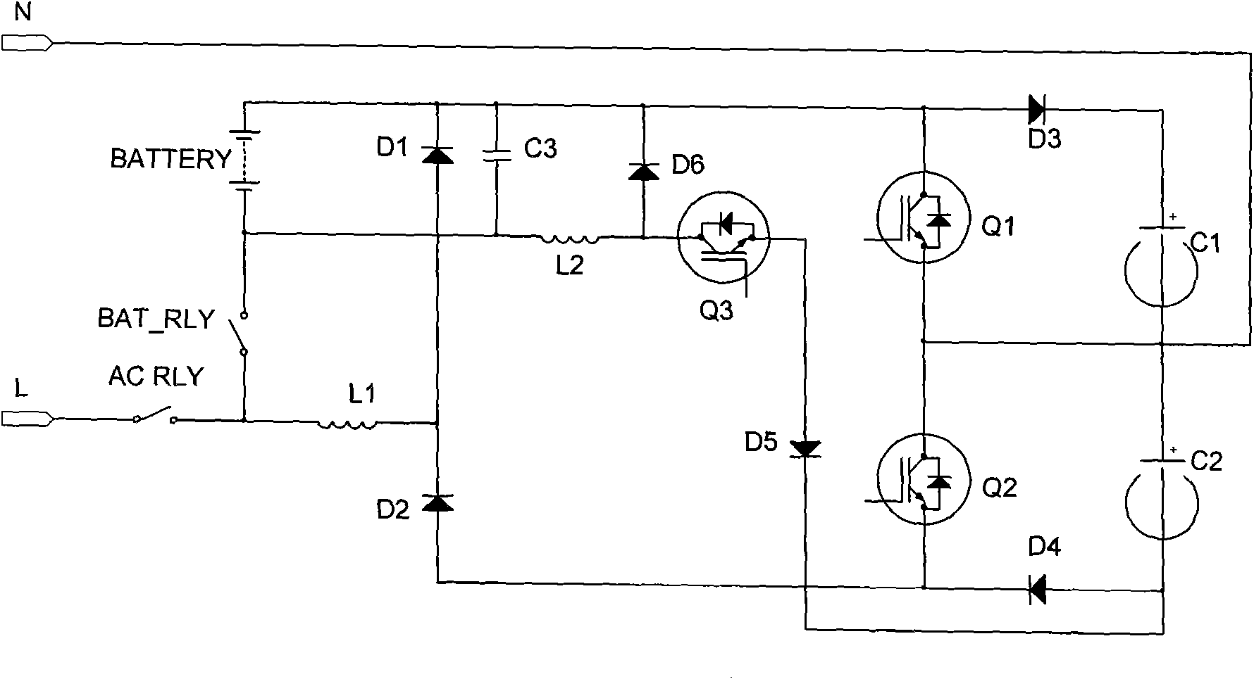
[0042] In Embodiment 1, the input terminal of the BUCK converter is coupled to the positive bus, the negative pole of the rechargeable battery is connected to the anode of the second diode D2, and the input terminal of the charger is connected to the cathode of the first diode D1. According to the symmetry of the circuit, the modification of the first embodiment can be obtained, please refer to figure 2 , this embodiment uses a negative Buck converter, and the difference from Embodiment 1 is that the cathode of the fifth diode D5 is the input terminal of the Buck converter, which is connected to the negative pole of the second electrolytic capacitor C2 and the fourth diode D4. Anode, so that the BUCK converter takes power from the negative bus; the anode of the fifth diode D5 is connected to the source of the third switching tube Q3, and the drain of the third switching tube Q3 is connected to one end of the second inductor L2 and the sixth diode The anode of the tube D6, the...


PUM


Abstract

The invention discloses an UPS battery charger. The charger comprises a rectification circuit, a PFC chopper circuit and a BUCK converter, wherein the input end of the rectification circuit is coupled with alternating current input live wire (L), the output end of the rectification circuit is coupled with the input end of the PFC chopper circuit, the output end of the PFC chopper circuit is coupled with alternating current input null line (N) through bus bar, the input end of the BUCK converter is coupled with the bus bar and the output end of the BUCK converter is coupled with a rechargeablebattery. The invention also discloses a UPS with the UPS battery charger. By using the UPS battery charger and the UPS of the invention, larger charging power can be realized by using one BUCK converter, the control method is simple so as to effectively reduce the production cost, and the input voltage of the UPS battery charger is stable.

Description

technical field [0001] The present invention relates to power supply technology, in particular to a UPS (Uninterrupted Power Supply, ie uninterrupted power supply) battery charger and a UPS with the UPS battery charger. Background technique [0002] With the increasing demand for data protection, UPS systems have been used more and more widely. In the UPS system, one of the important parts is the battery charger. The topology selection of the charger, especially the UPS in the small and medium power range (about 10KVA), has an important impact on the cost of the whole machine. [0003] At present, the topological solutions for small and medium power UPS chargers mainly include flyback or forward converters, etc., which take power through input AC, transform and isolate after rectification, and output power to the battery pack. Usually the design power of these conversion devices is relatively small (generally below 500W). If the battery capacity is relatively large and req...

Claims


Application Information

Patent Timeline
IPC IPC(8): H02J7/10H02J7/00
CPCY02P80/10
Inventor 豆飞进陈鹏崔彬邴阳
Owner VERTIV CORP
Why Eureka
Try Eureka