
Roller grill separating device

a technology of separating device and roller grill, which is applied in the direction of fruit coring, dough processing, fruit stoning, etc., can solve the problems of poor hot dog cooking, poor hot dog care, and damage to consumer confidence in a particular eating establishment, so as to reduce food borne contamination liability and maintain grill neatness

Inactive Publication Date: 2006-02-23
SPIRIT SPECIALTY SOLUTIONS
View PDF10 Cites 14 Cited by
  • Summary
  • Abstract
  • Description
  • Claims
  • Application Information

AI Technical Summary

Benefits of technology

[0013] An object of this invention is to provide a roller grill separating device that keeps grilled products in place and keeps uncooked products separated from cooked products on the grill so as to reduce food borne contamination liability and to maintain grill neatness at the same time.

Problems solved by technology

However, a problem arises in that the hot dogs can easily get ignored as the store clerk loses track of the time that each hot dog was originally placed on the grill.
This problem becomes even worse with the practice of staggering hot dog placement on the grill.
A poorly cooked hot dog can hurt or destroy a consumer's confidence in a particular eating establishment.
Moreover, a hot dog which is undercooked or overcooked presents a serious health concern for the consumer, and the U.S. Department of Health has taken a strong interest in this issue.
The problem with this type of grill sign is that they are not sanitary.
Further, the signs take up too much space on the grill which could be used for cooking.
In addition, the metal signs are hot to the touch, and therefore they cannot be moved easily and create a burning hazard to the operator.
Despite the critical importance of monitoring cooking time, none of the then existing devices helped the operator keep track of cooking time or elapsed time.
Although these inventions enabled grill operators to determine when the product is cooked, there are some problems left unsolved.
Therefore, cooked products and uncooked products are on the grill at the same time, and it is possible that uncooked products touch and contaminate cooked products.
Without an effective grill separating device, it is hard for a grill operator to organize and manage the grill.
It is also hard to identify which part is cooked and which part is uncooked, and which part is one type of products and which part is another.
Also, hot dog items can move or “walk” from side to side and away from their respective sign identifier thus confusing customers and operators and making the grill look unorganized.
There is presently no device that effectively separates cooked products from uncooked products or one kind of products from another.
Moreover, there is no device that effectively separates cooking area on a grill without taking cooking space and at the same time displays marketing information and the type of food product for the operator and consumers.

Method used


Image

  • Roller grill separating device
  • Roller grill separating device
  • Roller grill separating device

Examples


Embodiment Construction

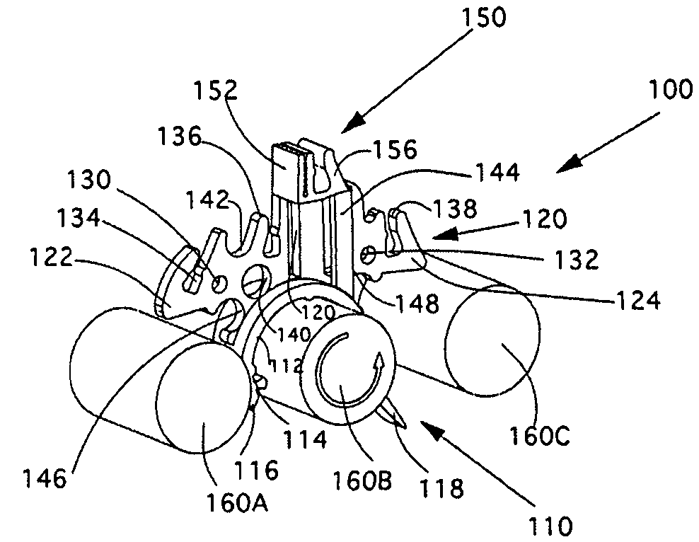
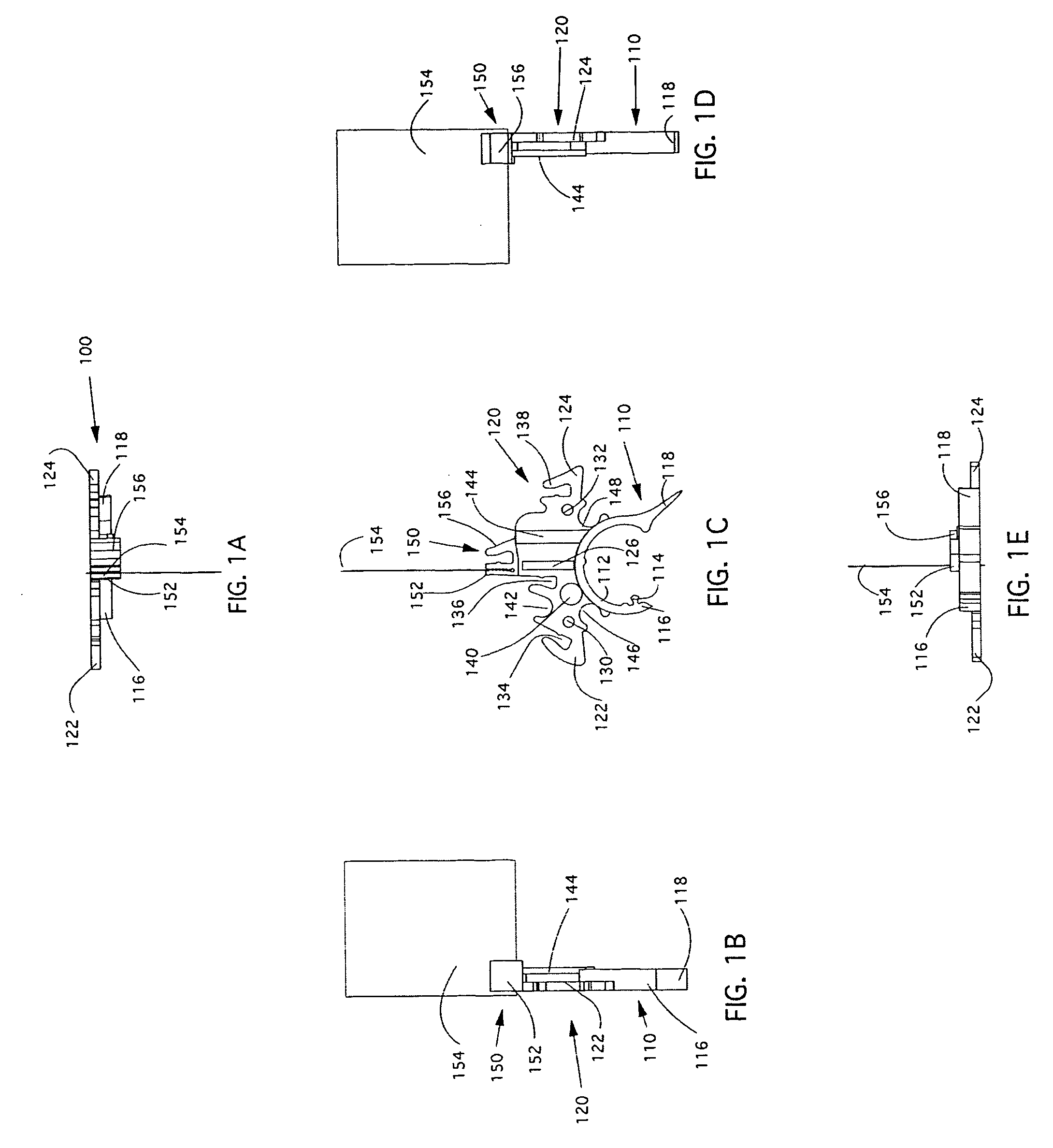
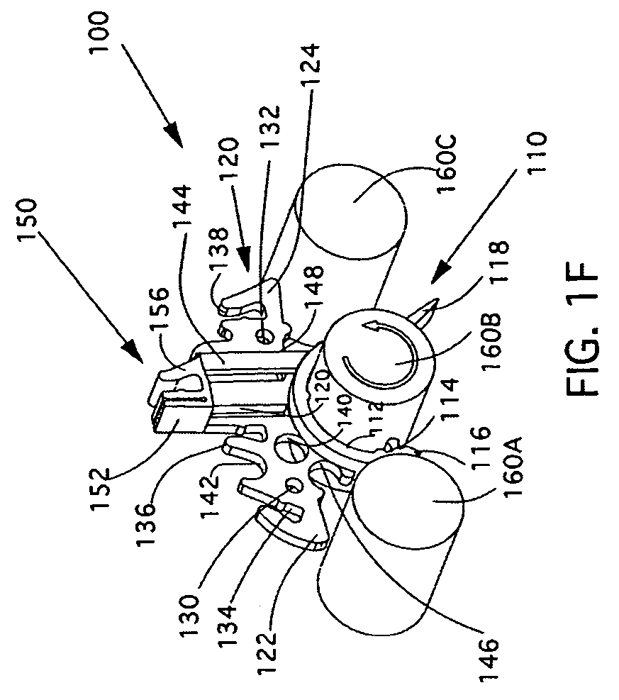
[0053] FIGS. 1A-F illustrate a roller grill separating device 100 comprising a clip 110, a center section 120, and upper sign clips 150 holding a sign 154. The clip 110 is in the shape of an arcuate clip-on member and is designed to fit onto a grill roller. Since the clip 110 is preferably made of FDA approved, heat resistant plastic, it is pliable enough to snap onto a grill roller. When correctly snapped onto place, as shown in FIG. 1F, inner circumference 112 of the clip 110 slides over a grill roller 160B. A precise inner diameter keeps roller scratching to a minimum. A projection 114 may be added to a front leg 116 to make the device 100 fit to thinner rollers. A flared portion of a rear leg 118 adds stability and keeps the device from rotating counter clockwise.

[0054] The center section 120 prevents rotation of the clip 110. In this position, the center section 120 keeps the device 100 in an upright position with ends 122, 124 resting on grill rollers 160A and 160C. The cente...


PUM


Abstract

A roller grill separating device having a clip capable of being attached to a grill roller, a center section, and upper sign clips to hold supplemental signage. The center section stabilizes the device and prevents it from rotating. The center section accommodates a cross bar, a separator bar, a thermometer, and signs. A plurality of devices can be used to form a wall or the device can be used with a separator bar and a crossover bar to create a separate area on the grill so that uncooked products do not touch cooked products. One or more device can be replaced with a flavor identification device. The flavor identification device includes a slide-in signage area for sign clips that are used for identifying and marketing different types of food products such as hot dogs. The device is inexpensive to make, is sanitary and made of a heat resistant material.

Description

CROSS REFERENCE TO RELATED APPLICATIONS [0001] This application is a continuation-in-part application of U.S. Design Patent Application No. 29 / 218,658 filed on Dec. 7, 2004, which is scheduled to issue on Oct. 25, 2005 as U.S. Design Patent No. D510,879, which is a divisional application of U.S. Design Patent Application No. 29 / 195,166 filed on Dec. 9, 2003, now U.S. Design Patent No. D499,346, which is a divisional application of U.S. Design Patent Application No. 29 / 169,616 filed on Oct. 24, 2002, now U.S. Design Patent No. D483,278, which is a continuation-in-part of U.S. patent application Ser. No. 09 / 845,835 filed on May 1, 2001, now U.S. Pat. No. 6,474,223, which is a continuation-in-part of U.S. patent application Ser. No. 29 / 127,846 filed on Aug. 15, 2000, now U.S. Design Patent No. D441,307, which is a continuation of U.S. patent application Ser. No. 09 / 280,815 filed on Mar. 30, 1999, now U.S. Pat. No. 6,101,927. The disclosures of U.S. patent application Ser. Nos. 09 / 280,8...

Claims


Application Information

Patent Timeline
IPC IPC(8): B26D3/11
CPCA47J37/0786
Inventor KURMLAVAGE, MICHAEL M.
Owner SPIRIT SPECIALTY SOLUTIONS
Learn More