Modular luminaire system

a module-type, luminaire technology, applied in the direction of lighting and heating apparatus, lighting support devices, coupling device connections, etc., can solve the problems of increasing the size of the luminaire, limiting the nature and aesthetic value of the prior art luminaire, and increasing the heat produced within the luminaire uni

Inactive Publication Date: 2006-02-23
PHILIPS LIGHTING NORTH AMERICA CORPORATION
View PDF25 Cites 80 Cited by
  • Summary
  • Abstract
  • Description
  • Claims
  • Application Information

AI Technical Summary

Benefits of technology

This patent describes a new kind of LED lights that can be easily installed without having to connect them all together yourself. Instead, they are designed with two parts: a lamp and a control box. These parts have different functions but work together seamlessly when put back together again. This makes it easier for people who don't know much about electricity to install these lights.

Problems solved by technology

The technical problem addressed by this patent is how to create a more flexible and aesthetically pleasing lighting system without requiring the ballast electronics to be integrated with the luminaire unit. This allows for separate components that can easily connect at different locations, making them easier to install and adjust while maintaining their individual appearances.

Method used


Image

  • Modular luminaire system
  • Modular luminaire system
  • Modular luminaire system

Examples


examples

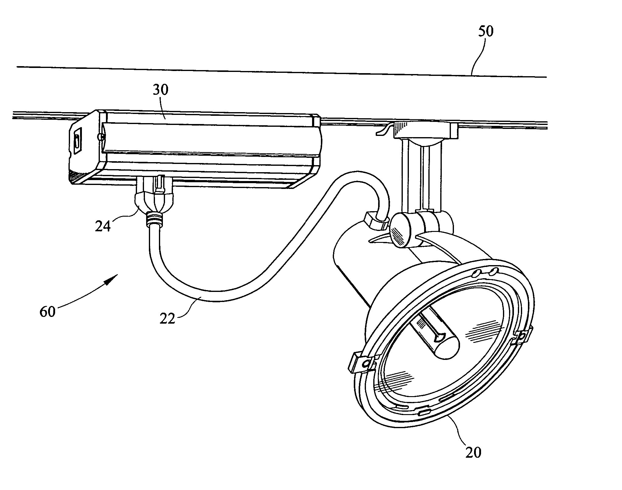
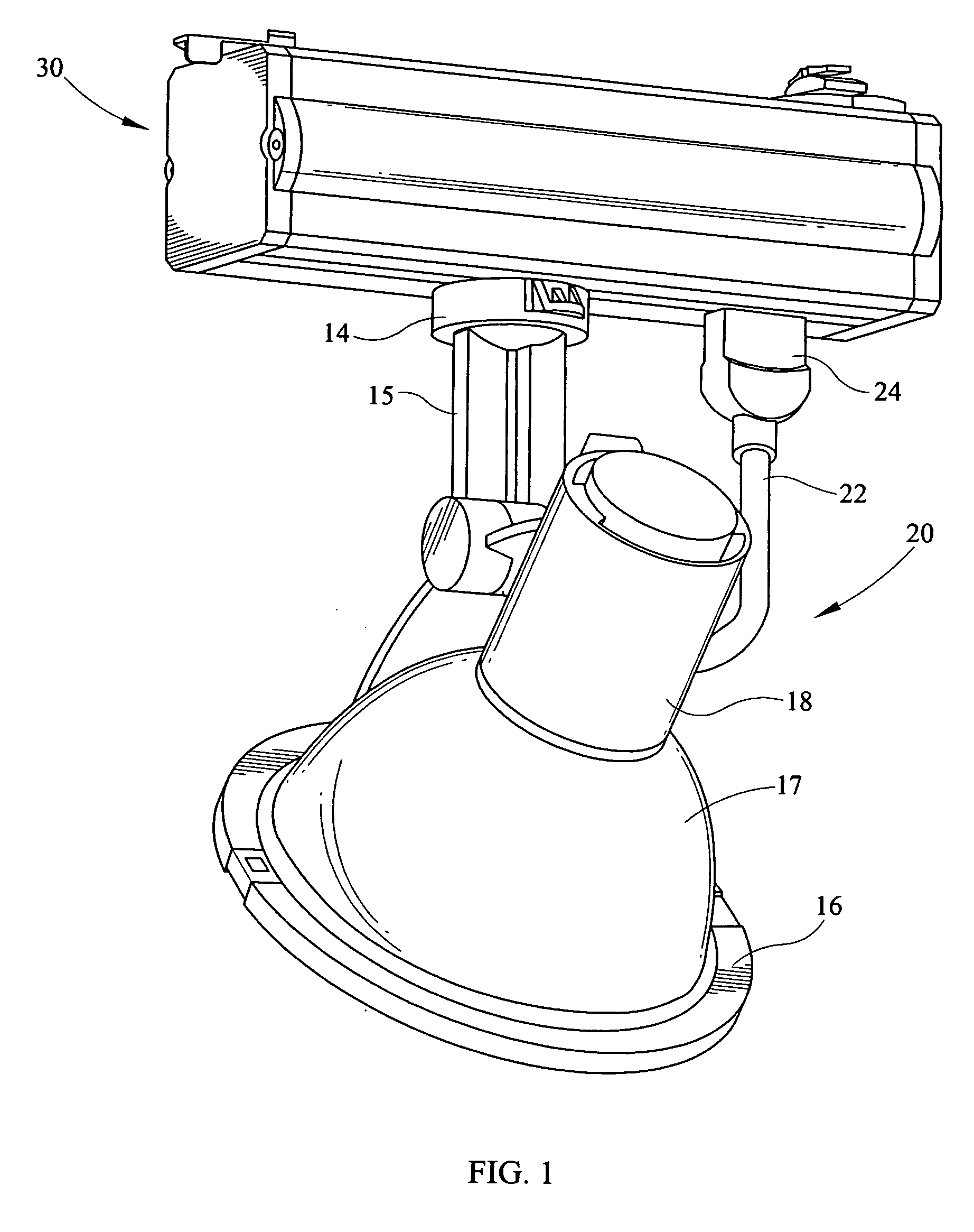
[0048] As is readily apparent, the ability of modularizing the luminaire units and the ballast electronics as is done in the present invention is through the use of a plug and cord assembly allows for significant variations in design and use of high intensity lamp illumination. Of the examples shown in FIGS. 15, 16 and 17, as well as throughout the rest of the Figures, it is apparent that the luminaire unit 20 may be remotely positioned away from the remote ballast housing and mounted on a number of mounting surfaces.

[0049] As is shown in FIG. 15, the luminaire unit 20 is mounted directly to a track 50, but is not electrically connected thereto. The luminaire unit 20 is electrically connected through the cord 22 and plug 24 to the remote ballast housing 30 which is electrically connected to the energized track 50. The modular HID luminaire unit 60, shown in FIG. 15, therefore depicts the luminaire unit adjacent to and electrically connected to the remote ballast housing but not mou...


PUM


Abstract

The modular track luminaire system of the present invention is a modular lighting system which has a lighting unit which is electronically connected to a remote ballast housing by a removable and reattachable insulated cord and plug system, the luminaire unit electrically connected to the ballast housing through the flexible cord and plug system thereby allowing the entire system to be modularized.

Description


Claims


Application Information

Patent Timeline
Owner PHILIPS LIGHTING NORTH AMERICA CORPORATION
Why Eureka
Try Eureka