Control valve for variable displacement compressor

a compressor and variable-discharge technology, applied in the direction of positive-discharge liquid engines, pump components, machines/engines, etc., can solve the problems of large control valve scale, inability to perform rotational speed control, and inability to achieve the desired characteristics with eas

Inactive Publication Date: 2006-02-23
TGK
View PDF1 Cites 3 Cited by
  • Summary
  • Abstract
  • Description
  • Claims
  • Application Information

AI Technical Summary

Benefits of technology

[0014] The present invention has been made in view of these problems, and an object thereof is to provide a control valve for a variable displacement compressor, based on a Pd−Ps differential pressure control method, which is capable of setting characteristics concerning the degree of influence of crank pressure on a change in the differential pressure between discharge pressure and suction pressure, to desired characteristics with ease.

Problems solved by technology

A compressor used in a refrigeration cycle of an automotive air conditioner is driven by an engine whose rotational speed varies depending on a traveling condition of the vehicle, and hence incapable of performing rotational speed control.
However, to perform the displacement control based on the suction pressure Ps as described above, it is necessary to movably arrange a flexible member, such as a diaphragm or a bellows, for sensing the suction pressure Ps in the control valve, which tends to make the control valve relatively large in scale.
Although the phenomenon may not be ideal when considering only the characteristics of the control valve, this is not always true when considering matching between the Pd−Ps differential pressure control and control of the variable displacement compressor.
This makes it difficult to perform the displacement control with stability.
For example, when the swash plate of the variable displacement compressor is difficult to move, it is required to increase the response to improve motion of the swash plate, whereas when the swash plate is excessively easy-to move, it is required to lower the response to stabilize motion of the swash plate.
However, when the characteristic of the spring or the attractive force characteristic of the solenoid is changed as described above, the differential pressure characteristics, i.e. the relationship between the value of electric current supplied to the solenoid and the differential pressure (Pd−Ps) can also be changed, which makes it difficult to perform a total tuning operation.

Method used


Image

  • Control valve for variable displacement compressor
  • Control valve for variable displacement compressor
  • Control valve for variable displacement compressor

Examples


Embodiment Construction

[0021] Hereinafter, an embodiment of the present invention will be described in detail with reference to the drawings.

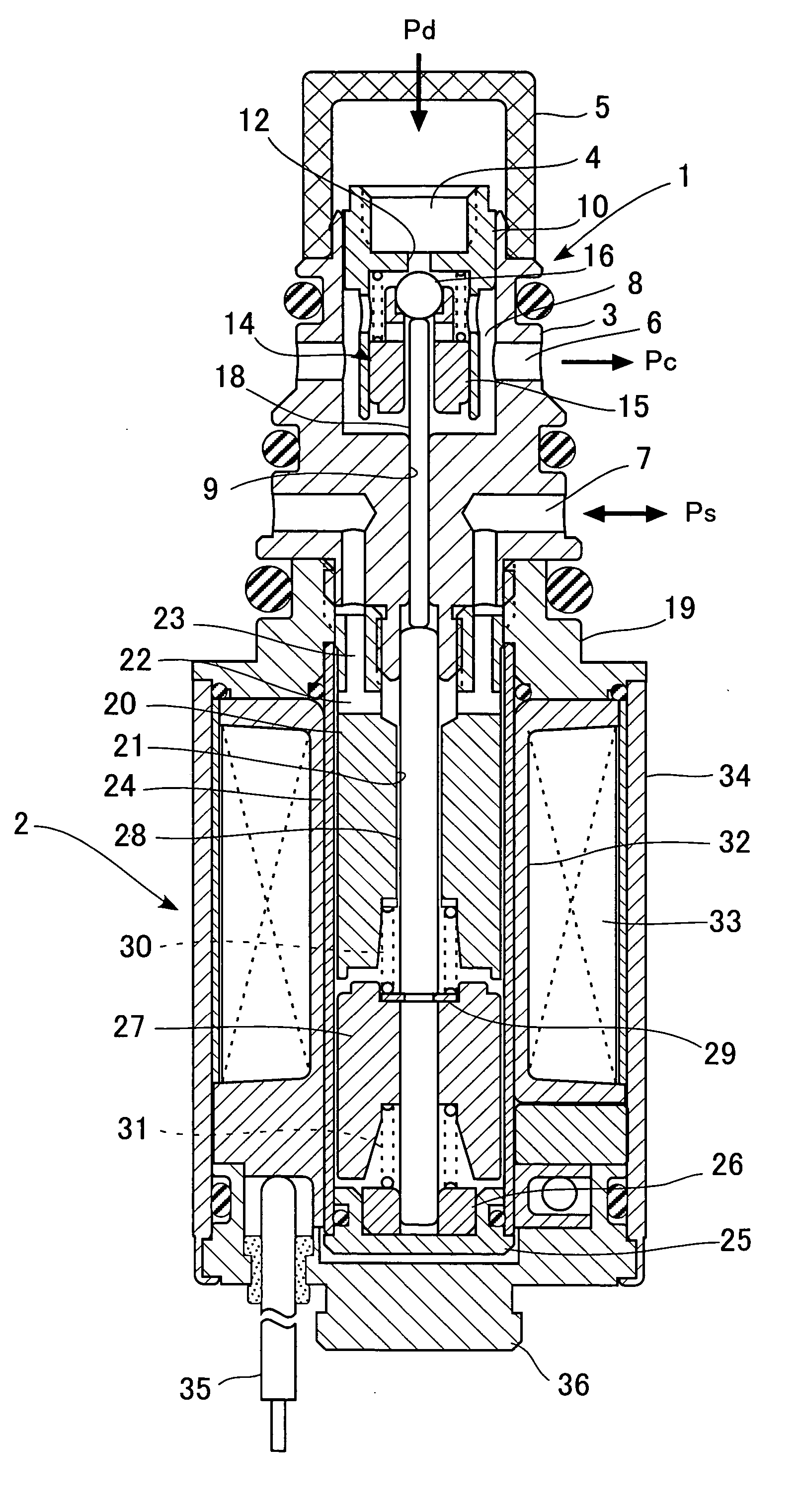
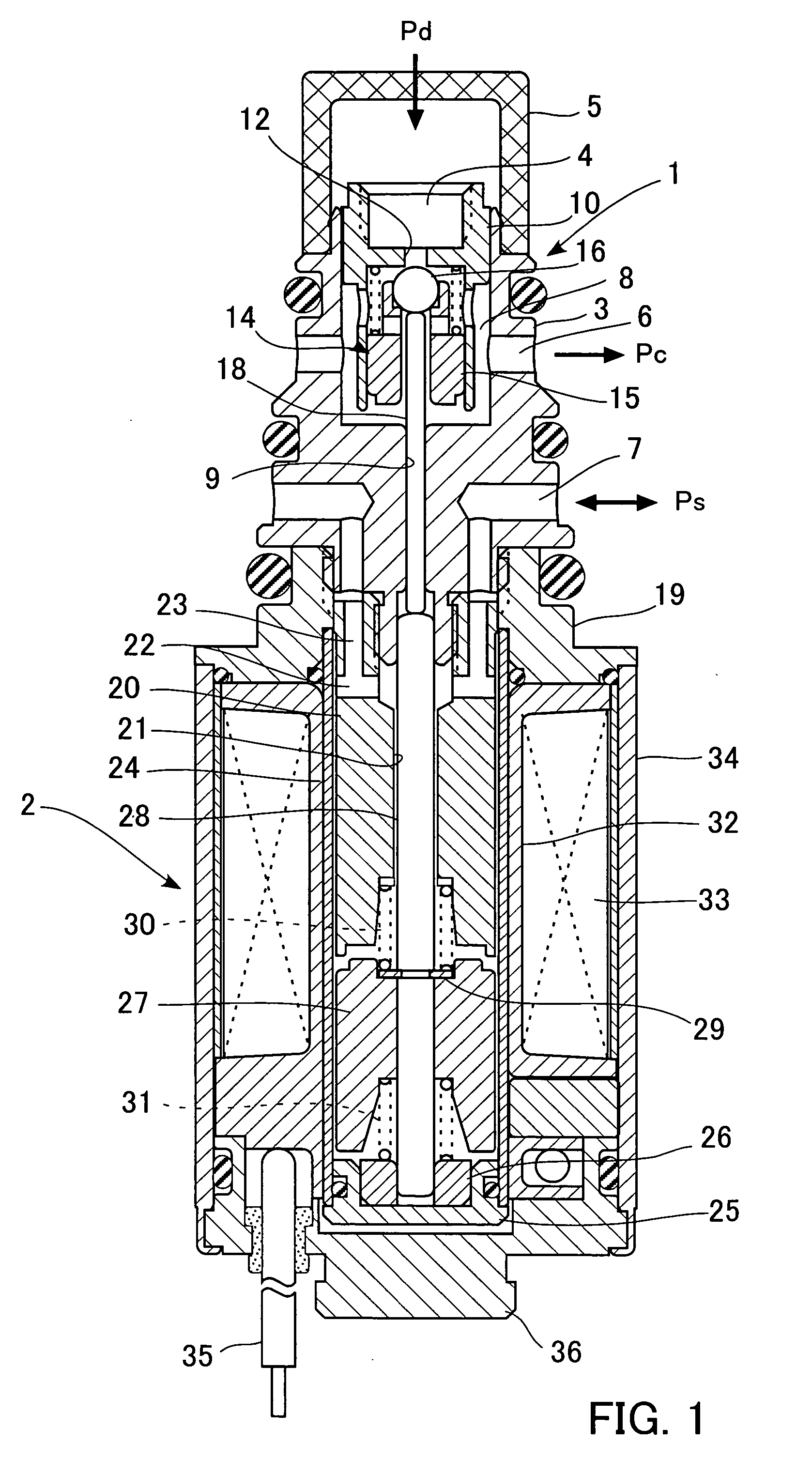
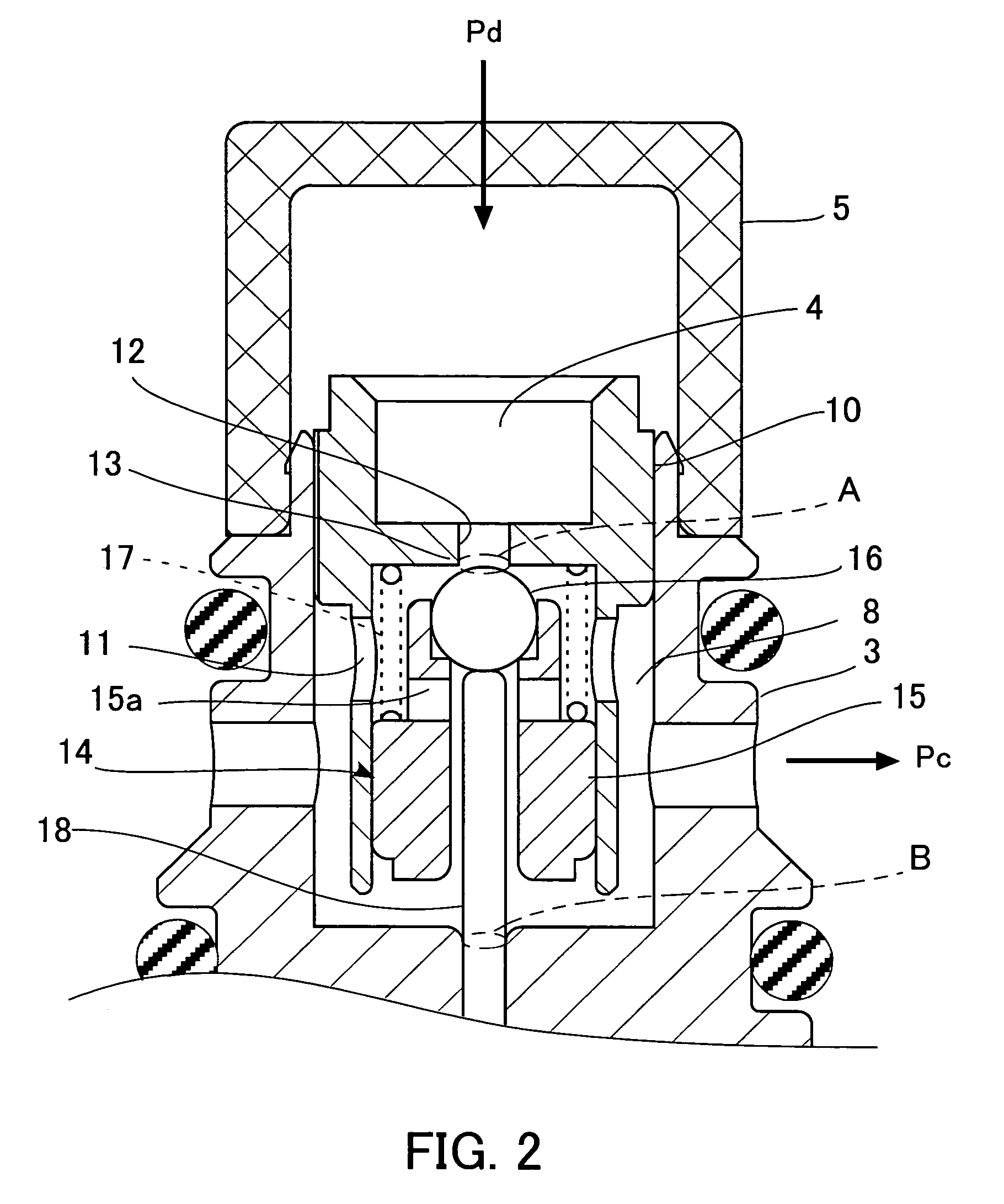
[0022]FIG. 1 is a cross-sectional view showing the arrangement of a control valve for a variable displacement compressor, according to the present embodiment, and FIG. 2 is a fragmentary expanded cross-sectional view of an upper part of the FIG. 1 control valve.

[0023] Referring first to FIG. 1, the control valve introduces part of refrigerant discharged from a variable displacement compressor, not shown, and allows the introduced refrigerant to flow into a crankcase while controlling the flow rate thereof. The control valve is formed by integrally assembling a valve-forming section 1 containing a valve section for adjusting the flow rate of refrigerant, and a solenoid 2 for controlling the valve lift of the valve section.

[0024] The valve-forming section 1 has a stepped hollow cylindrical upper body 3 having an open upper end defining therein a discharge pressure p...


PUM


Abstract

To provide a control valve for a variable displacement compressor, based on a Pd−Ps differential pressure control method, which is capable of setting characteristics concerning the degree of influence of crank pressure on a change in the differential pressure between discharge pressure and suction pressure, to desired characteristics with ease. A control valve for a variable displacement compressor adjusts the difference between an effective pressure-receiving area A on a discharge pressure side of an intermediate in which a valve element and a shaft are integral with each other and an effective pressure-receiving area B on a suction pressure side of the intermediate, as required. This makes it possible to obtain desired differential pressure·crank pressure characteristics according to the specifications of the control valve. Changes in the effective pressure-receiving areas have almost no influence on electric current·differential pressure characteristics, i.e. the relationship between the value of electric current supplied to a solenoid and the differential pressure between discharge pressure and suction pressure, and hence it is possible to realize the changes in the effective pressure-receiving areas with ease.

Description

CROSS-REFERENCES TO RELATED APPLICATIONS, IF ANY: [0001] This application claims priority of Japanese Application No. 2004-239161 filed on Aug. 19, 2004 and entitled “CONTROL VALVE FOR VARIABLE DISPLACEMENT COMPRESSOR”.BACKGROUND OF THE INVENTION [0002] (1) Field of the Invention [0003] The present invention relates to a control valve for a variable displacement compressor, and more particularly to a control valve for a variable displacement compressor, for controlling a discharge capacity of refrigerant discharged from a variable displacement compressor for an automotive air conditioner. [0004] (2) Description of the Related Art [0005] A compressor used in a refrigeration cycle of an automotive air conditioner is driven by an engine whose rotational speed varies depending on a traveling condition of the vehicle, and hence incapable of performing rotational speed control. To eliminate the inconvenience, a variable displacement compressor capable of changing the discharge capacity of...

Claims


Application Information

Patent Timeline
Patent Type & Authority Applications(United States)
IPC IPC(8): F04B1/26F04B27/08
CPCF04B27/1804F04B2027/1859F04B2027/1854F04B2027/1827F04B27/14F04B39/10
Inventor YOSHIHIRO, RYOSUKE
Owner TGK
Why Eureka
Try Eureka