Common mode filter

a filter and common mode technology, applied in the direction of waveguides, line-transmission details, waveguide type devices, etc., can solve the problems of difficult signal passing, high impedance of two conducting wires, easy noise influence of transmission, etc., and achieve the effect of simplifying the structur

Active Publication Date: 2014-12-30
ELMEC
View PDF9 Cites 4 Cited by
  • Summary
  • Abstract
  • Description
  • Claims
  • Application Information

AI Technical Summary

Benefits of technology

[0040]According to the common mode filter of a first aspect of the present invention with such a structure, a pair of conductive lines are formed on the first dielectric layer for transmitting the differential signal, with the first dielectric layer interposed between them, and the first divided floating grounds are formed in a state of facing the conductive lines and being divided into a plurality of numbers in the length direction, with the first passive two-terminal network connected between the first divided floating grounds at the input side or the output side of the first divided floating grounds, and the external ground potential. Therefore, the distribution constant type differential transmission line for the differential signal is formed by the conductive lines and the first divided floating grounds, and a series resonance circuit for the common mode signal is formed by the conductive lines and the first passive two-terminal network. Then, in the ultra high-speed differential transmission line, a desirable ultra high-speed differential signal can be passed successfully, while cutting-off and absorbing inside an undesirable common mode signal.
[0041]According to the common mode filter of another aspect of the present invention, a pair of the first divided floating grounds are formed at the input side and the output side. Therefore, in addition to the above-described effect, the structure is simplified.
[0042]According to the common mode filter of another aspect of the present invention, three or more first divided floating grounds are formed. Therefore, various attenuation characteristics of the common mode signal can be obtained.
[0043]According to the common mode filter of another aspect of the present invention, the first divided floating grounds have the first passive two-terminal network connected between all adjacent grounds or a part of the adjacent grounds. Therefore, various attenuation characteristics for the common mode signal can be obtained.
[0044]According to the common mode filter of another aspect of the present invention, common first passive two-terminal networks are connected to the plurality of adjacent first divided floating grounds. Therefore, various attenuation characteristics of the common mode signal can be obtained.
[0045]According to the common mode filter of another aspect of the present invention, the conductive lines are formed into meander shapes. Therefore, in addition to the above-described effect, delay characteristics of a desirable ultra high-speed differential signal can be arbitrarily set.

Problems solved by technology

In the high-speed serial transmission, a voltage amplitude needs to be reduced for shortening a rise time, and therefore this transmission easily receives an influence of a noise.
However, in the differential transmission system, a function of canceling the common mode signal such as an outside noise is insufficient, and therefore a common mode chalk coil is inserted into a differential transmission line, for preventing its adverse influence.
Meanwhile, in a case of the common mode signal, currents flow through the two conducting wires, with the same phases, thus generating the magnetic flux in the magnetic body, and the impedance of the two conducting wires becomes high, to make it difficult to pass the signals.

Method used


Image

  • Common mode filter
  • Common mode filter
  • Common mode filter

Examples


Embodiment Construction

[0071]Preferred embodiments of the present invention will be described hereafter, with reference to the drawings.

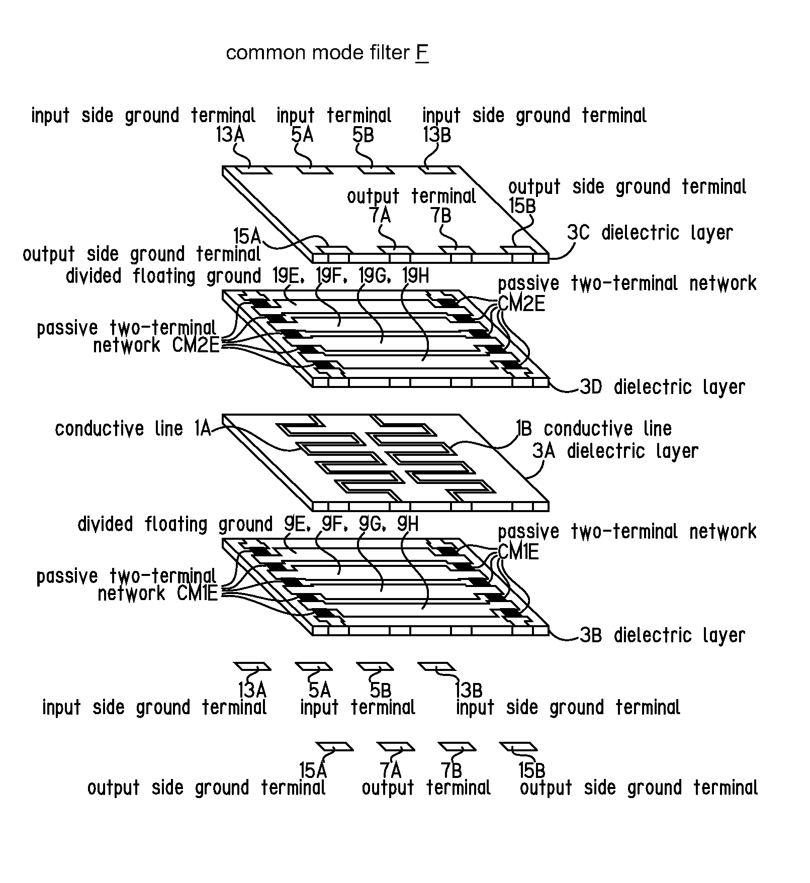
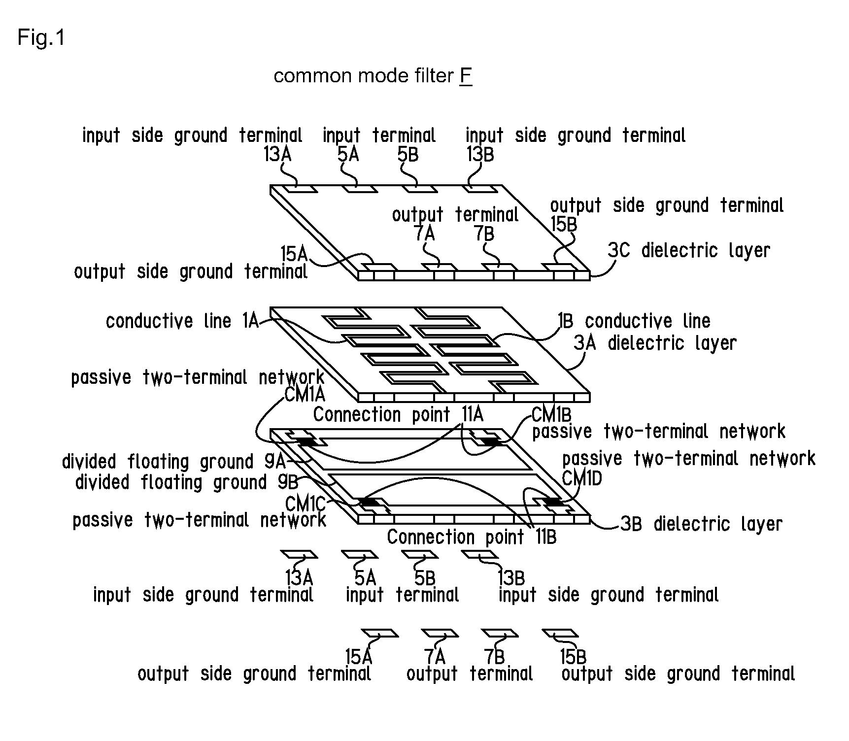
[0072]FIG. 1 is an exploded perspective view showing a basic structure of a common mode filter F according to the present invention.

[0073]In FIG. 1, a pair of rectangular meander conductive lines 1A and 1B are farmed between both opposite edges of the dielectric layer 3A on one surface (on an upper surface in FIG. 1) of a rectangular dielectric layer 3A which is composed of a dielectric substrate such as baked ceramics, by a conventionally known printing method. The conductive lines 1A and 1B are connected to input terminals 5A and 5B, and output terminals 7A and 7B formed on different opposite edges of the dielectric layer 3A. In the figure, such input terminals 5A, 5B, and output terminals 7A, 7B are shown in parts different from the part of the dielectric layer 3A, for convenience.

[0074]The conductive lines 1A, 1B, and the input / output terminals 5A, 5B, 7A, 7B are arra...


PUM

PropertyMeasurementUnit
widthaaaaaaaaaa
frequencyaaaaaaaaaa
resistanceaaaaaaaaaa

Abstract

To sufficiently attenuate a common mode signal by passing an ultra-high speed differential signal through an ultra-high speed differential transmission line. A common mode filter comprises: a pair of conductive lines formed on a first dielectric layer to transmit a differential signal; a plurality of first divided floating grounds in a state of being separated from an external ground potential, and facing the conductive lines, with the first dielectric layer interposed between them, and formed by being divided into a plurality of numbers in a length direction of the conductive lines, and forming a distribution constant type differential transmission line for the differential signal, together with the conductive lines; and a first passive two-terminal network connected between the first divided floating grounds located at least at an input side or an output side of the first divided floating grounds, and the external ground potential.

Description

BACKGROUND OF THE INVENTION[0001]1. Technical Field of the Invention[0002]The present invention relates to a common mode filter, and particularly relates to a new common mode filter that secures a passage of an ultra high-speed differential signal propagated through an ultra high-speed differential transmission line, and attenuates a common mode signal.[0003]2. Description of Related Art[0004]In recent years, high-definition video contents such as “HDTV: high definition television” and “Blue-ray Disc” become widespread, and in order to transmit a vast amount of digital data for supporting such contents, high-speed serial transmission has been used.[0005]In the high-speed serial transmission, a voltage amplitude needs to be reduced for shortening a rise time, and therefore this transmission easily receives an influence of a noise. Therefore, in order to hardly receive the influence of the noise, a differential transmission of a signal is generally used.[0006]In a differential transmi...

Claims


Application Information

Patent Timeline
Patent Type & Authority Patents(United States)
IPC IPC(8): H03H7/42H01F17/00H03H1/00H01P1/203
CPCH03H7/427H01F17/0006H01P1/20345H03H2001/0085H01P1/2039
Inventor KAMEYA, MASAAKI
Owner ELMEC
Why Eureka
Try Eureka