
X-ray scatter image reconstruction by balancing of discrepancies between detector responses, and apparatus therefor

a scatter image and detector response technology, applied in the field of x-ray and density imaging of objects, can solve problems such as matching calculated discrepancies, and achieve the effects of non-linearity of the inverse problem, and reducing the instability of the iterative process

Active Publication Date: 2006-03-02
UNIVERSITY OF NEW BRUNSWICK
View PDF61 Cites 17 Cited by
  • Summary
  • Abstract
  • Description
  • Claims
  • Application Information

AI Technical Summary

Benefits of technology

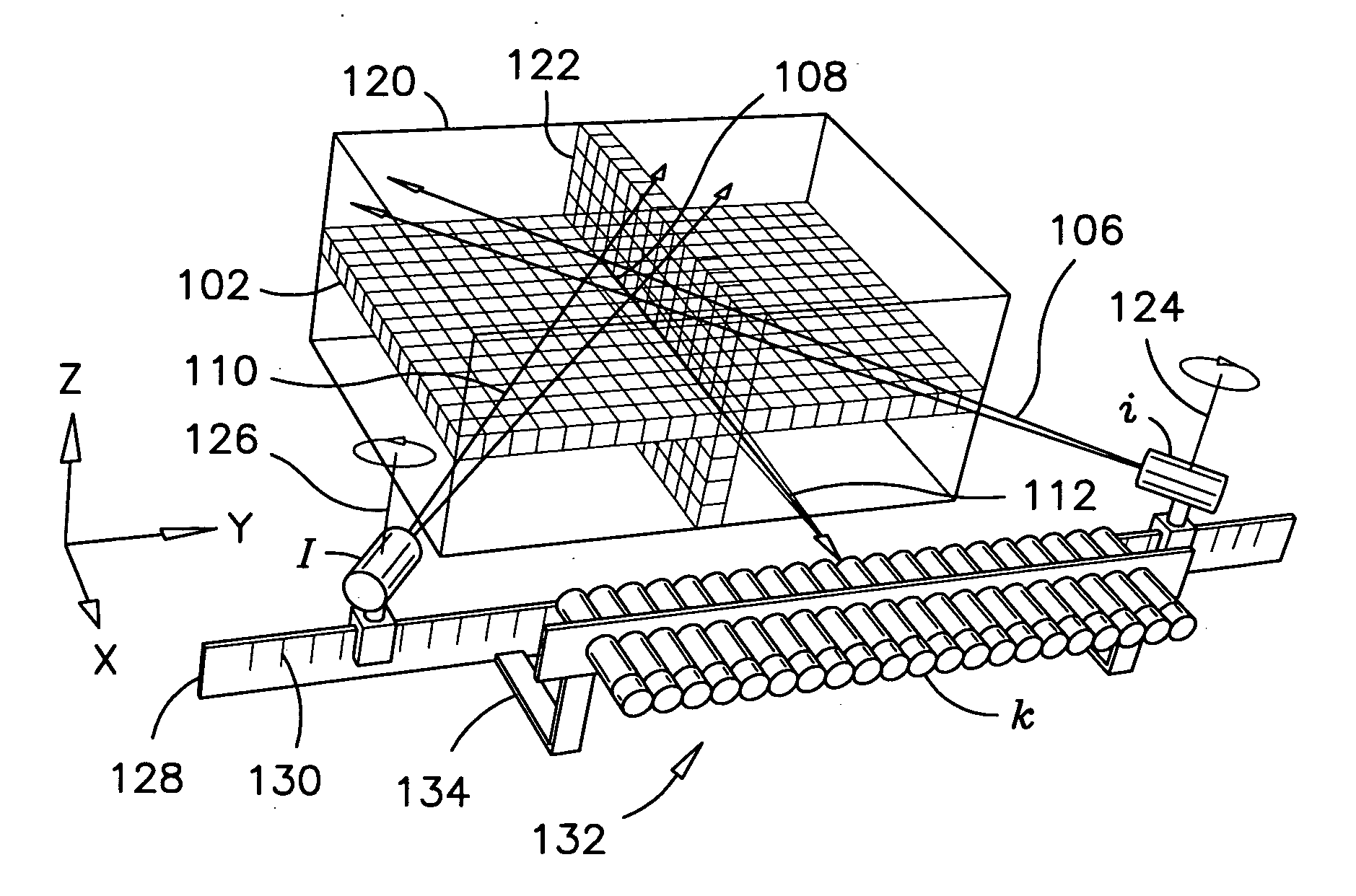
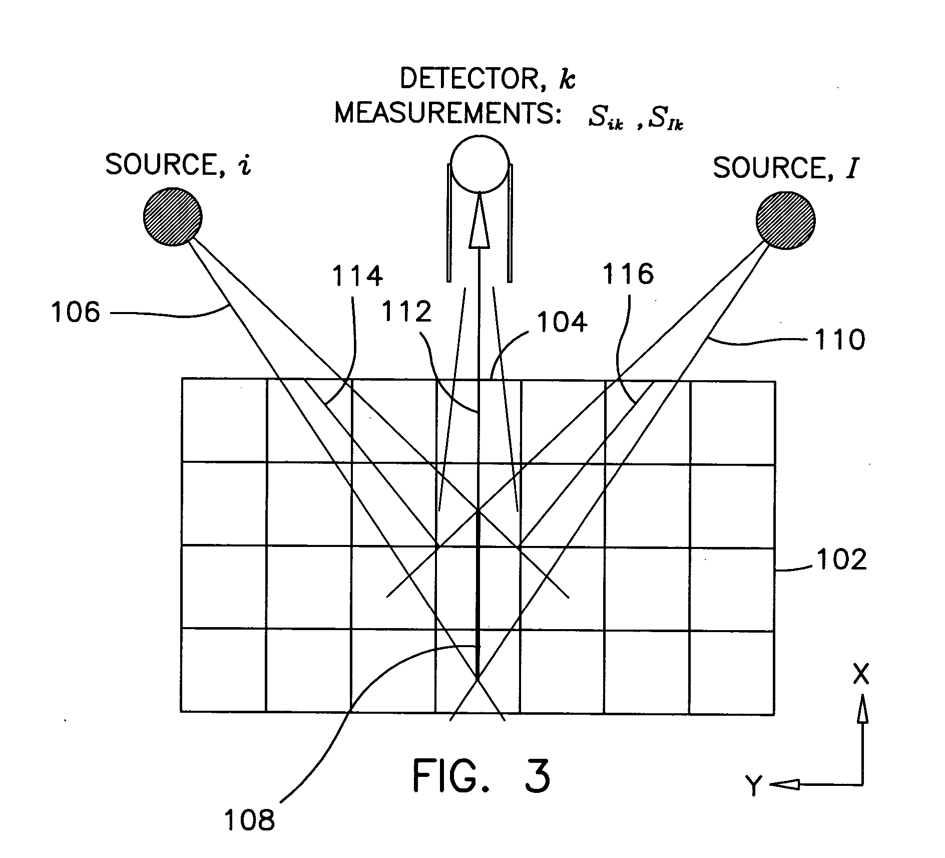
The present invention provides a method and apparatus for non-linear image reconstruction using ratios of similar non-linear values. This method involves irradiating an object with radiation beams and obtaining scattered radiation measurements. The measurements are taken with a detector that has a sight axis extending through the object. The method involves formulating ratios with the measurements and using those ratios instead of the actual measurements to reduce the impact of non-linearity. The apparatus includes a first collimated detector and a first radiation source along with a second radiation source and a second detector. The detectors and the radiation sources are movable in unison in a direction perpendicular to or parallel with the plane to scan the object entirely from one side. The technical effects of this invention include reducing the impact of non-linearity, improving image quality, and simplifying the image reconstruction process.

Problems solved by technology

The inverse problem consequently, consists of matching calculated discrepancies.

Method used


Image

  • X-ray scatter image reconstruction by balancing of discrepancies between detector responses, and apparatus therefor
  • X-ray scatter image reconstruction by balancing of discrepancies between detector responses, and apparatus therefor
  • X-ray scatter image reconstruction by balancing of discrepancies between detector responses, and apparatus therefor

Examples


Embodiment Construction

[0059] While this invention is susceptible of embodiments in many different forms, there are shown in the drawings and will be described in details herein one specific embodiment of a method to do x-ray imaging of thick objects from one side of the object and one preferred embodiment of an apparatus for x-ray imaging of objects, and for carrying out the preferred method. It should be understood that the present disclosure is to be considered as examples of the principles of the invention and is not intended to limit the invention to the embodiments illustrated and described. Furthermore, although x-ray and cone and fan beams are mentioned herein, it will be appreciated that the method and apparatus according to the preferred embodiments can also be used with pencil beams, with gamma rays and fast neutrons.

[0060] Similarly, it should also be appreciated, that the detector described herein can be collimated by physical means or by software means using energy measurement or time of fl...


PUM

PropertyMeasurementUnit
attenuation coefficientaaaaaaaaaa
diverging angleaaaaaaaaaa
densityaaaaaaaaaa

Abstract

The present invention pertains to a method and an apparatus to generate a density image of an object using fan or cone beams of radiation and collimated detectors on one side of the object. The method consists of irradiating an object with a plurality of pairs of non-parallel radiation beams wherein the beams in each pair intersect a same segment along the axis of the detector. Compton-scattering radiation from the beams are then measured, and corrected attenuation coefficients along each beam are obtained. This latter step is effected by taking a first ratio of detector measurements for the beams in each pair; comparing the first ratio with a second ratio of corresponding calculated detector measurements and balancing discrepancies between the first and second ratios in a forward-inverse numerical analysis algorithm. Taking ratios of attenuation coefficients along related incident beams eliminates non-linearity problems whereby the aforesaid algorithm can be solved.

Description

[0001] This application claims the benefit of provisional application Ser. No. 60 / 604,684, filed Aug. 27, 2004.FIELD OF THE INVENTION [0002] This invention pertains to x-ray, density-imaging of objects, and more particularly this invention pertains to x-ray, density-imaging using pairs of radiation sources scattering to a same detector, and a method to generate density images comprising the step of balancing discrepancies between detector responses, to overcome non-linearity problems. BACKGROUND OF THE INVENTION [0003] The use of numerical analysis to determine attenuation of radiation traversing or scattering out of an object has been used since the 1950's. This science has always had its limits and its use remains to the present a considerable challenge. Since powerful computers are now readily available at reasonable price, however, and that the associated mathematics are better understood, numerical calculation methods have been more commonly used to generate density images of o...

Claims


Application Information

Patent Timeline
Patent Type & Authority Applications(United States)
IPC IPC(8): G01N23/201G01T3/00G01J1/42G01T1/00
CPCG01N23/20008
Inventor ARSENAULT, PAULHUSSEIN, ESAM
Owner UNIVERSITY OF NEW BRUNSWICK
Learn More