Base station, mobile station and control method therefor

a mobile station and base station technology, applied in power management, transmission monitoring, multiplex communication, etc., can solve the problems of deterioration in communication quality, interference, and difficulty in completely preserving the orthogonality of all the spreading codes used

Inactive Publication Date: 2006-03-02
NEC CORP
View PDF4 Cites 91 Cited by
  • Summary
  • Abstract
  • Description
  • Claims
  • Application Information

AI Technical Summary

Benefits of technology

[0036] A exemplary object of the present invention is to solve the problems described above and provide a comm

Problems solved by technology

However, it is difficult to completely preserve the orthogonality of all of the spreading codes used, and in practice the respective despread codes are not completely orthogonal with each other and have components that correlate with other codes.
These correlating components constitute interference components at the time of communication, causing deterioration in communication quality.
Accordingly, as the number of communication entities increases, the interference also increases.
Hence, a situation arises in which a signal from a mobile station that is close to a base station imparts interference to a faint signal of a mobile station located at a distance from the base station.
For a base station that receives a signal with insufficient power, the number of errors in reception of the signal may increase.
When an error occurs in reading the TPC information transmitted by a mobile station, the downlink transmission power control at the base station malfunctions, resulting in a phenomenon, called power drift, in which the transmission power is not controlled in accordance with the TPC information that the mobile station transmitted to the base station.
Thus, the problem of the risk of a sudden call disconnection in a SHO state due to a power drift is not solved.
Thus, the problem of the risk of a sudden call disconnection in a SHO state due to a

Method used


Image

  • Base station, mobile station and control method therefor
  • Base station, mobile station and control method therefor
  • Base station, mobile station and control method therefor

Examples


embodiment 2

[0138] The second exemplary embodiment of the present invention is now described. In order to avoid redundant description, a description of parts that are same as those in the first exemplary embodiment of the present invention is omitted and a description is provided of only those parts that are different to the first exemplary embodiment.

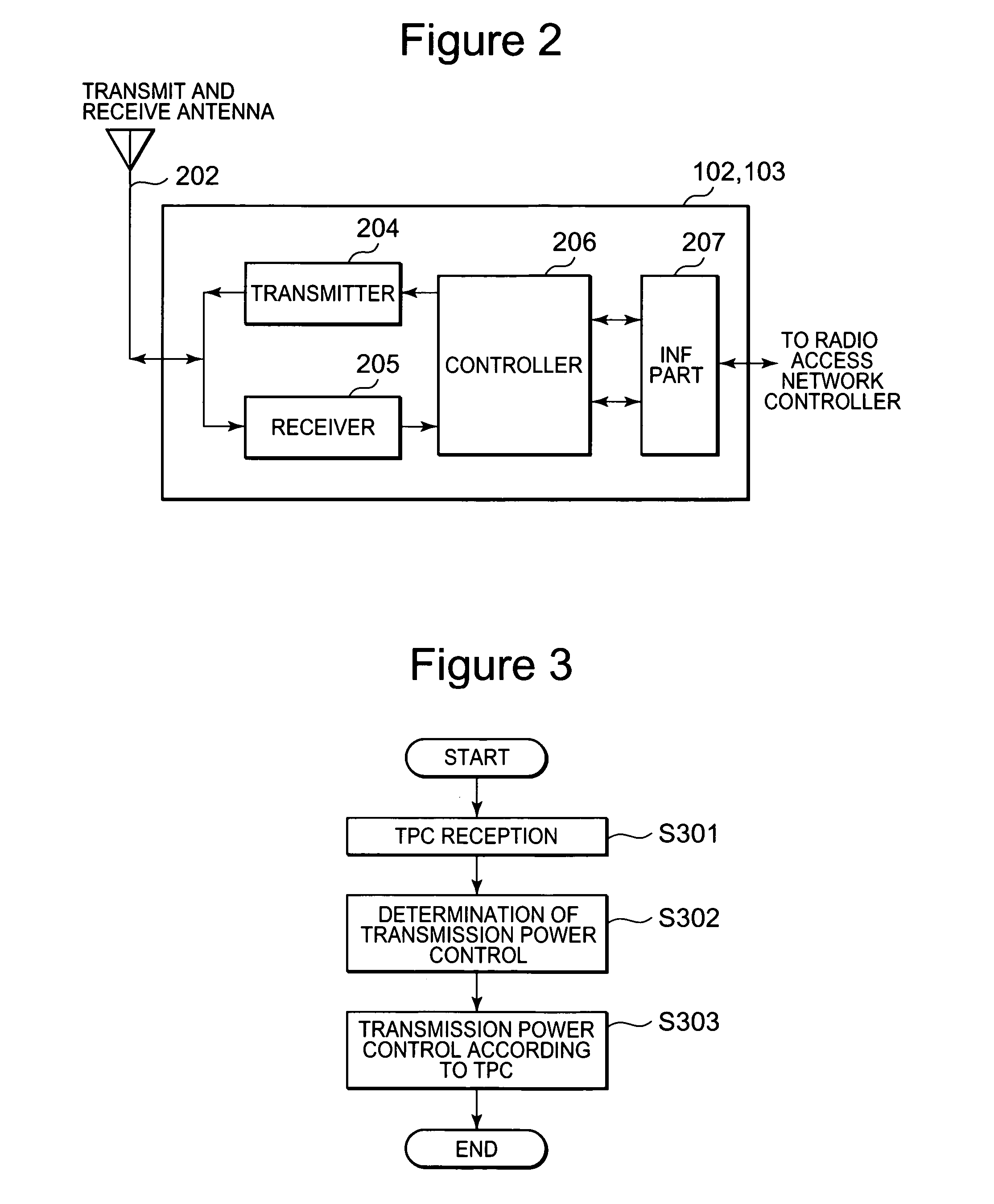
[0139] A difference between the first exemplary embodiment and the second exemplary embodiment is contents of the processing corresponding to S302 of FIG. 3. FIG. 7 is a flowchart of processing relating to the second exemplary embodiment.

[0140] Principle differences between the two exemplary embodiments are an addition of a step (S701) that determines whether or not the mobile station 101 is in a SHO state as well as a correction processing (S704) that is performed when the mobile station 101 is not approaching and the base station 202 does not provide the best path.

[0141] By previously adding the step of determining a SHO (S701) state, the pro...

embodiment 3

[0154] A third exemplary embodiment of the present invention is now described. Unlike the two exemplary embodiments described above, the third exemplary embodiment relates to a mobile station.

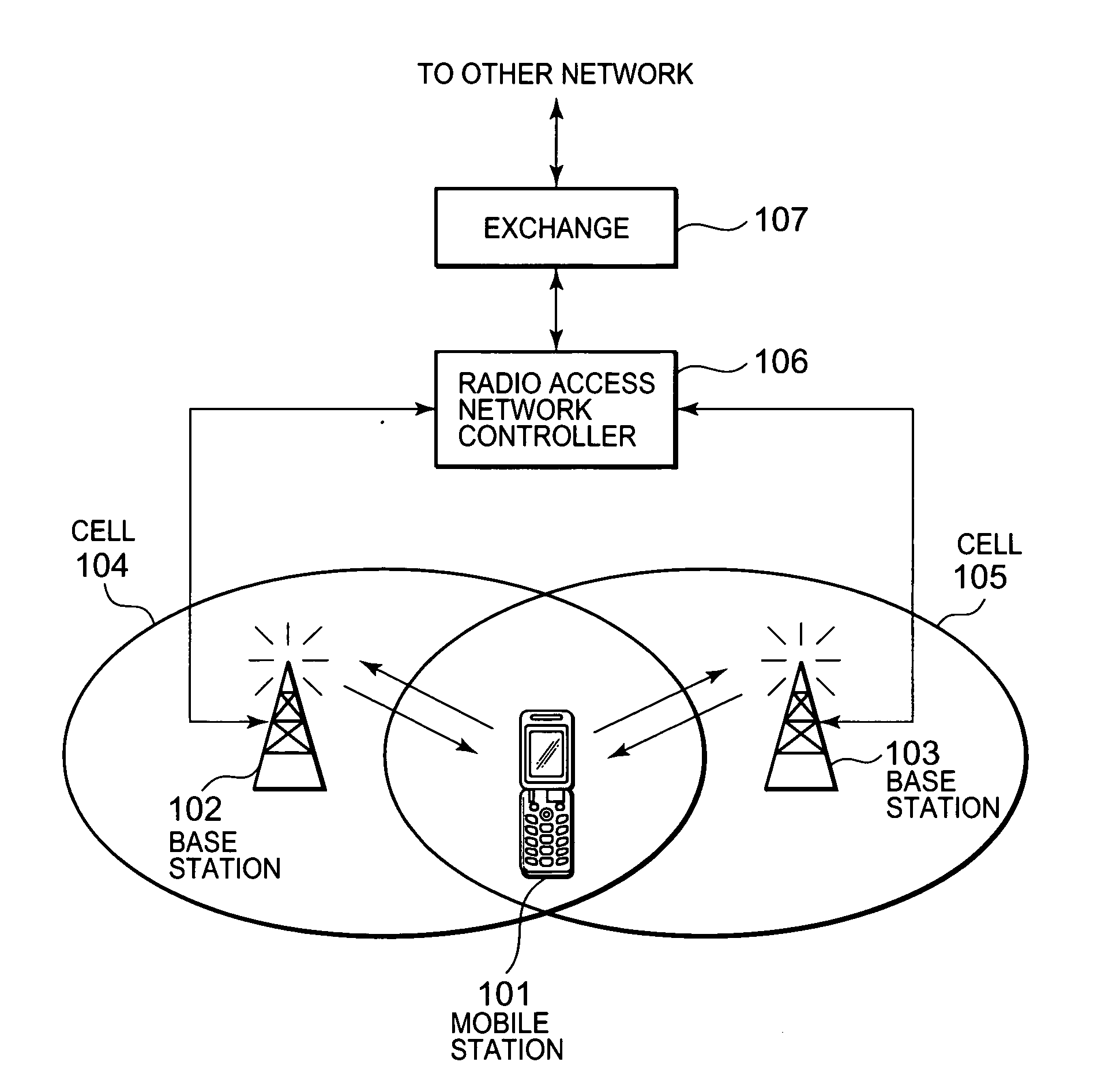
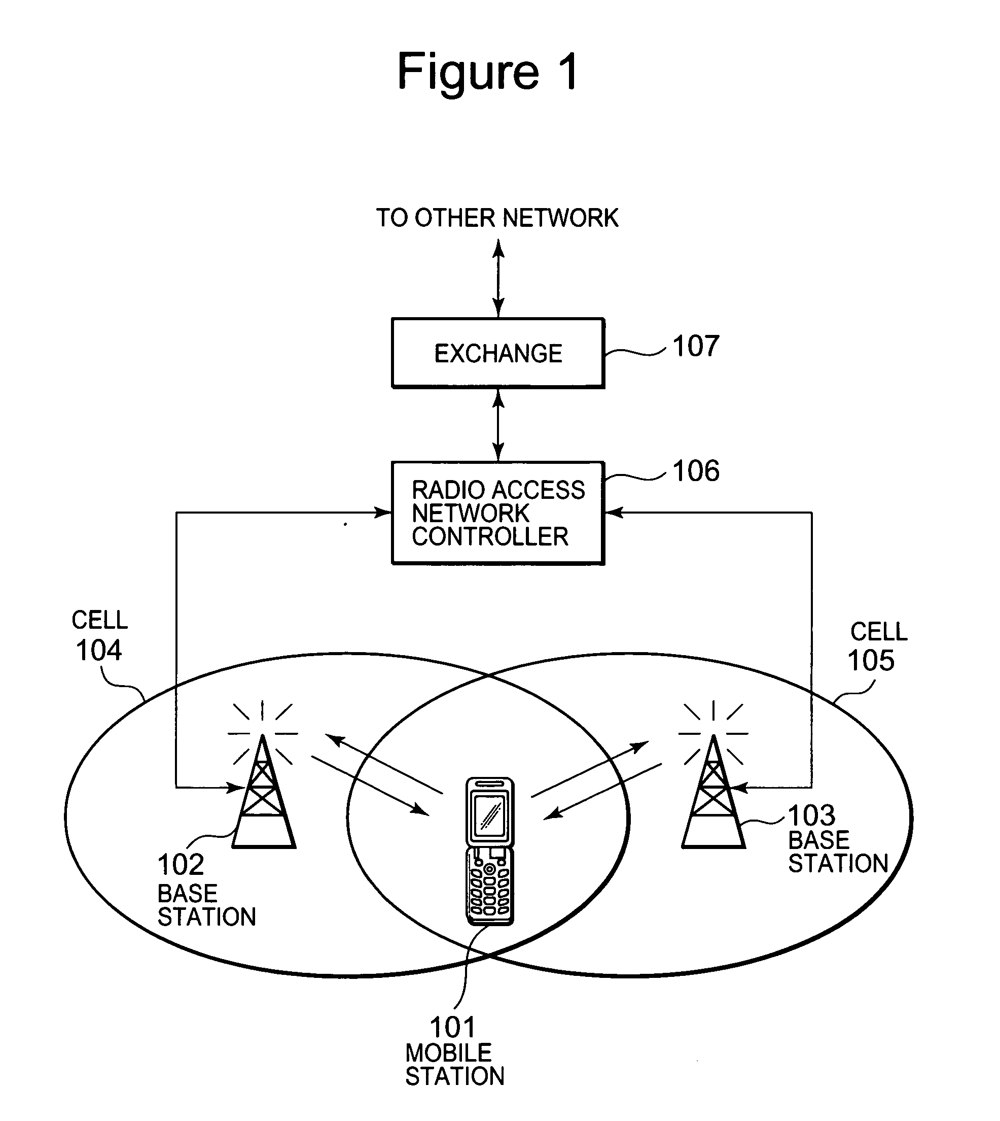
[0155] Similarly to the foregoing two exemplary embodiments, a system that applies this exemplary embodiment is shown in FIG. 1. To avoid redundancy, a description of FIG. 1 is omitted here.

[0156]FIG. 8 is a block diagram of principal functions of the mobile station 101 of the third exemplary embodiment of the present invention. A mobile station 101101 of FIG. 8 corresponds to the mobile station 101 of FIG. 1. The mobile station 101 comprises a transmit and receive antenna 802, a receiver 804, a transmitter 805, a controller 806, a speaker 807 and a micro phone 808.

[0157] The transmit and receive antenna 802 is an antenna that transmits and receives radio signals from the base station 102 and 103, and it is used for communication with the base stations 102 and 103.

[0158] The transmitter 805...

embodiment 4

[0190] A fourth exemplary embodiment of the present invention will now be described. The fourth exemplary embodiment relates to setting a path (i.e., a base station) with which a mobile station performs transmit power control. In order to avoid redundant description, a description of parts same as those in the third exemplary embodiment of the present invention is omitted here and a description is given of only parts different to those in the third exemplary embodiment.

[0191] The fourth exemplary embodiment will be described referring to FIG. 11. FIG. 11 is a flowchart illustrating a setting of a path (i.e., a base station) with which the mobile station 101 performs downlink transmit power control.

[0192] The mobile station 101 measures reception power of dedicated CHs transmitted from a plurality of base stations (S1101), and sets a path (a base station among the plurality of base station) with which the mobile station 101 performs downlink transmit power control based on informat...


PUM


Abstract

An exemplary method for a communication network according to the present invention includes detecting movement of a mobile station, and modifying a control for the communication network based on the detection of the movement. In an exemplary embodiment, a transmit power control may be increased or decreased based the movement of the mobile station which is detected. Further, the network may determine a base station among plurality of base stations which provides the best communication path, taking into account a movement state of the mobile station. Accordingly, a stable hand over process may be realized, providing favorable communication quality and minimizing the occurrence of disconnection of the mobile terminal from a base station.

Description

[0001] This application claims priority to Japanese Patent Application 2004-253927, the disclosure of which is incorporated herein by reference. BACKGROUND OF THE INVENTION [0002] 1. Technical Field [0003] The present invention relates to a transmit power control method in a wireless communication system, and a base station and a mobile station used for the transmit power control. [0004] 2. Background Art [0005] Terminals (wireless communication terminals) for wireless communication, such as mobile phones, PHS, PDA, pagers or wireless LAN connection devices have become popular, and increased expansion of service areas for the wireless communication and more diversification of services are expected. [0006] There are various types of wireless communication system based on wireless communication technology, such as the TDMA (Time Division Multiple Access) system and the CDMA (Code Division Multiple Access) system. Here, the CDMA system will be described as a representative thereof. [00...

Claims


Application Information

Patent Timeline
IPC IPC(8): H04Q7/20H04W36/18H04W36/36H04W52/04H04W52/28H04W52/36H04W52/40
CPCH04W52/28H04W52/282H04W52/40H04W52/285H04W52/362H04W52/283
Inventor KOGURE, YUKI
Owner NEC CORP
Why Eureka
Try Eureka