Controller system for downhole applications

a control system and downhole technology, applied in the direction of position/direction control, fluid removal, survey, etc., can solve the problems of reducing the output production of wells, affecting the motor and/or the pump, and comprenant the production fluids themselves

Inactive Publication Date: 2006-03-09
OILFIELD EQUIP DEVMENT CENT
View PDF1 Cites 67 Cited by
  • Summary
  • Abstract
  • Description
  • Claims
  • Application Information

AI Technical Summary

Problems solved by technology

As the natural downhole pressure of a well decreases, the well bore tends to fill up with liquids, such as oil and water, which block the flow of the formation gas into the borehole and reduce the output production from the well in the case of a gas well and comprise the production fluids themselves in the case of an oil well.
Failure to control the head pressure can result in conditions that adversely effect the motor and / or the pump.
Left unattended, these conditions can cause damage to the pump and / or motor.
Despite their effectiveness, the viability of VSDs is hampered by significant adverse effects that occur during their operation.
One adverse effect is the introduction of harmonics.
Harmonics are undesirable because they can cause damage to peripheral devices (e.g., household appliances such as televisions, microwaves, clocks and the like) that are serviced by the power company supplying power to the VSD.
As a result, some power companies have placed restrictions on the use of VSDs.
In addition to the damage caused to peripheral devices, the pump motor and associated power cable may themselves be damaged.
Specifically, the high peak-to-peak voltage spikes caused by switching the VSD transistors increases the motor temperature and can damage the motor power transmission cable (due to the large difference between the spike voltage and the insulation value of the cable).
As a result, the chance for premature equipment failure is increased.

Method used


Image

  • Controller system for downhole applications
  • Controller system for downhole applications
  • Controller system for downhole applications

Examples


Embodiment Construction

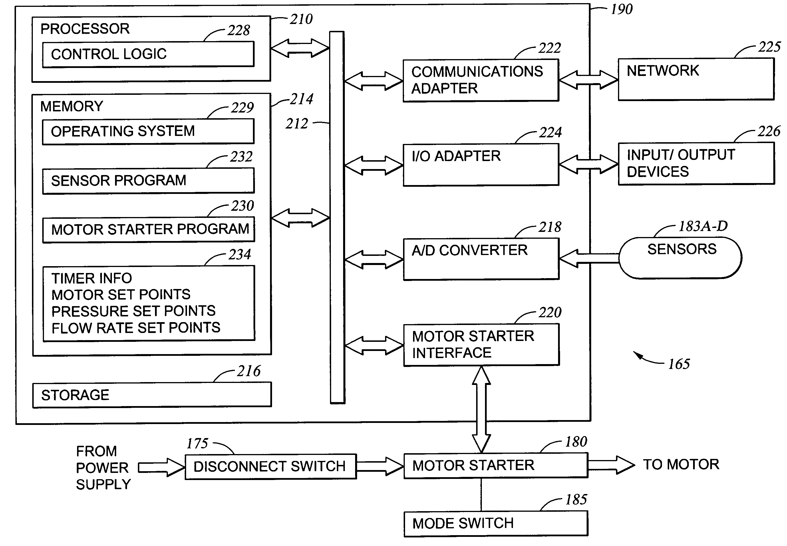
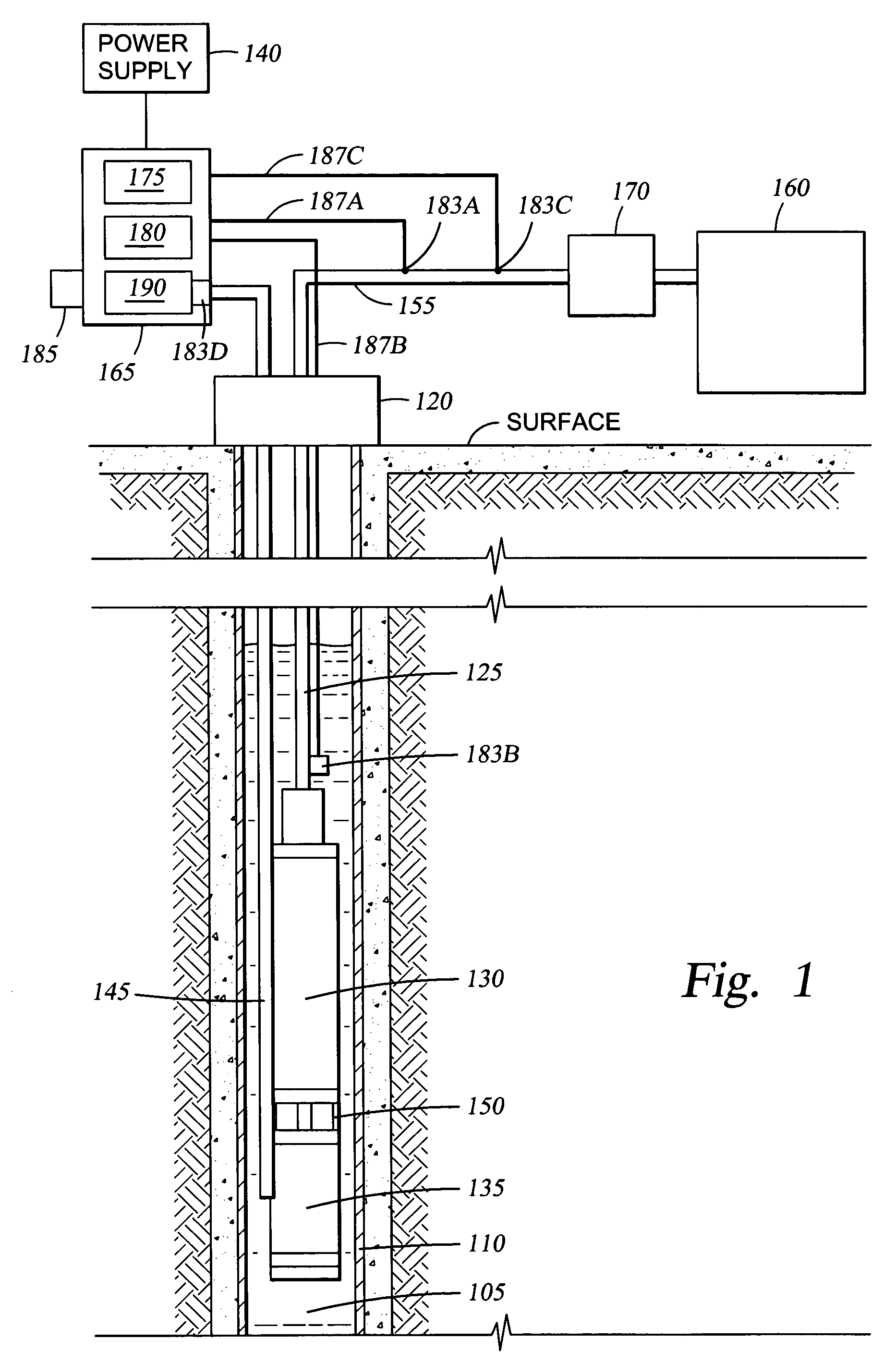
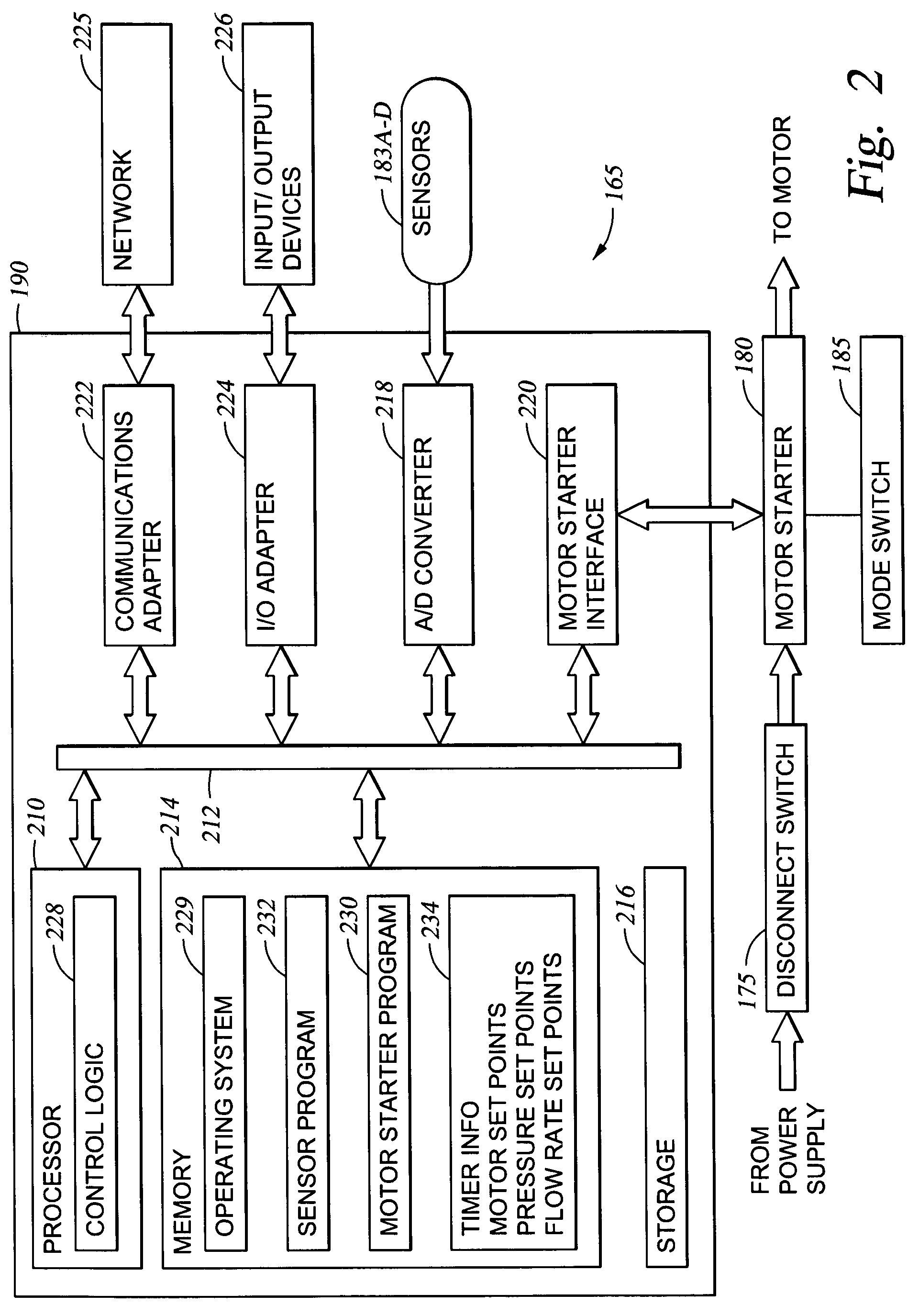
[0020] The present invention provides a closed feedback system for operating peripheral devices (e.g., a flow controller) in response to operating information (e.g., environmental conditions). Illustrative operating information includes well bore pressure, line pressure, flow rates, fluid levels, and the like. The following embodiment describes the operation of a flow controller disposed in a fluid line in response to operating variable values, e.g., pressure / flow readings taken in the flow line and the well bore. The pressure / flow measurements are then compared to target values. If necessary, the flow controller is closed or opened to control the rate of fluid flow through the line and thereby achieve the desired target values. In some situations a pump motor may be halted is the target values cannot be achieved. However, embodiments of the invention are not limited to controlling a flow controller or to measuring pressure / flow. For example, in another embodiment, motor operation v...


PUM


Abstract

The present invention generally provides a closed feedback system for operating peripheral devices in response to environmental conditions. Illustrative environmental conditions include well bore pressure, line pressure, fluid levels, flow rates and the like. In one embodiment, a flow controller disposed in a fluid line is operated in response to operating variable readings (e.g., pressure and / or flow rate) taken in the flow line and / or a well bore. The variable measurements are then compared to target values. If necessary, the flow controller is closed or opened to control the rate of fluid flow through the flow line and thereby achieve the desired target values. In another embodiment, the operation of a pump motor is monitored. Operating variables, such as voltage, current and load, are measured and compared to target values. In the event of a difference between the actual values of the variables and the target values, the flow controller is adjusted to affect the head pressure on a pump being driven by the motor. In some cases, the motor operation may be halted or otherwise adjusted.

Description

CROSS-REFERENCE TO RELATED APPLICATIONS [0001] This application is a continuation of co-pending U.S. patent application Ser. No. 09 / 704,260, filed Nov. 1, 2000. The aforementioned related patent application is herein incorporated by reference in its entirety.BACKGROUND OF THE INVENTION [0002] 1. Field of the Invention [0003] The present invention relates generally to closed-loop feedback systems. More specifically, the invention relates to a controller system configured to adjust the operation of peripheral devices in response to pre-selected operating variables. [0004] 2. Description of the Related Art [0005] The production of fluids (e.g., water and hydrocarbons) from wells (e.g., coal methane beds and oil wells) involves technologies that vary depending upon the characteristic of the well. While some wells are capable of producing under naturally induced reservoir pressures, more commonly encountered are well facilities which employ some form of an artificial lift production proc...

Claims


Application Information

Patent Timeline
Patent Type & Authority Applications(United States)
IPC IPC(8): G05D11/00E21B34/16E21B43/12E21B47/00
CPCE21B34/16E21B47/0007E21B43/128E21B43/12Y10T137/0324E21B47/008
Inventor BASSETT, LONNIE
Owner OILFIELD EQUIP DEVMENT CENT
Why Eureka
Try Eureka