
System and method for utility metering and leak detection

a technology of system and method, applied in the field of system and method of electronic utility (e. g., water and gas) metering and leak detection, can solve the problems of difficult leak detection, unusually high bills, and other waterline leaks that go undetected

Active Publication Date: 2006-03-23
GOOGLE LLC
View PDF10 Cites 148 Cited by
  • Summary
  • Abstract
  • Description
  • Claims
  • Application Information

AI Technical Summary

Benefits of technology

The system and method described in this patent detects leaks of water and gas by monitoring usage patterns. It uses sensors to detect the presence of leaks by looking for patterns where water or gas is always being used, even at a low rate. The severity of the leak is indicated by the minimum amount of usage during a given time period. The monitoring system can also interrupt utility service if usage exceeds a set maximum during a given time period. Overall, this system helps to prevent leaks and reduce excessive water and gas usage.

Problems solved by technology

This makes it difficult to test for leaks, since there is no predictable time during the day or night that water usage drops to zero.
However, other waterline leaks go undetected until a water bills become unusually high or water damage is discovered.
Gas leaks are potentially more dangerous than water leaks, and can be more difficult to detect.
Owners of large apartment buildings and commercial buildings face additional problems in monitoring water usage and leak detection.
Moreover, the plumbing and sprinkler systems of such structures tend to be more complex than the systems found in a residence.
Thus, any inefficiencies in the usage of utilities is magnified in a large commercial structure, and the costs of such inefficiencies are magnified.
The management of a large commercial building often does not have an accurate accounting of water usage by the various systems.
A maintenance issue as minor as a broken irrigation sprinkler head can cause increased and unnecessary water usage.
Conventional water and gas meters used in connection with residential and commercial structures measure the total amount of water or gas used, but do not monitor the usage patterns.
Thus, conventional meters do not provide the information needed to detect leaks.
Excess gas usage can occur, for example, if a thermostat fails, if a pool heater is left on accidentally, if a stove is left on accidentally, etc.

Method used


Image

  • System and method for utility metering and leak detection
  • System and method for utility metering and leak detection
  • System and method for utility metering and leak detection

Examples


Embodiment Construction

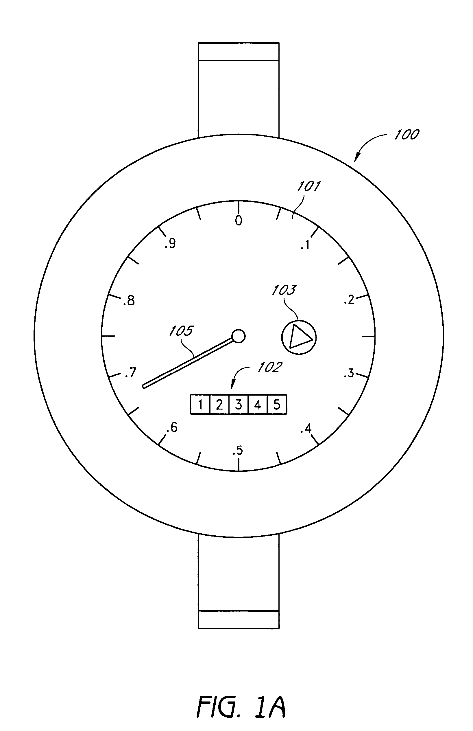
[0027]FIG. 1A shows a dial face of a typical water meter register 100. The register includes a digital indicator 102 that reads water used in cubic ft, a radial dial 101 and radial hand 105 that indicate water usage between 0 and 1 cu ft, and a low-flow indicator 103 that makes several rotations for each rotation of the radial hand 10S.

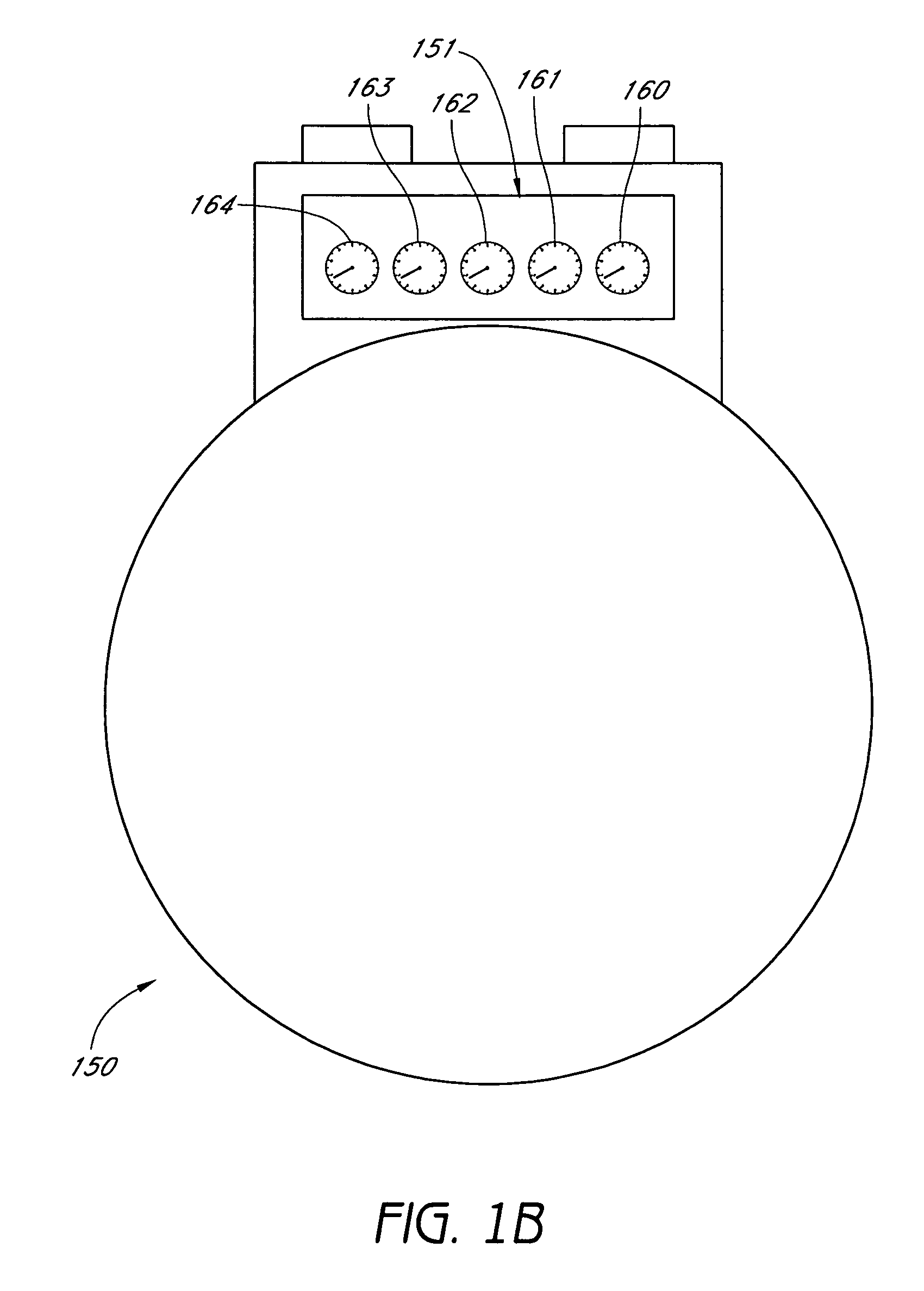
[0028]FIG. 1B shows a typical gas meter 150. In the meter 150, a group of radial dials 160-164 display digits corresponding to gas usage in cubic ft. In FIG. 1B, the lest-significant digit is displayed by the dial 160 and the most significant digit is displayed by the dial 164. The dial 160 is similar in effect to the low-flow indicator 103.

[0029] Historically, the utility meters shown in FIGS. 1A and 1B were read manually on periodic basis. Many communities have converted to Automatic Meter Reading (AMR) systems wherein the register is read electronically and remotely. The Automatic Meter Reading system allows the utility company to save on meter r...


PUM


Abstract

The system and method for detecting water and / or gas leaks by monitoring usage patterns is described. In one embodiment, the existence of a leak is detected by looking for usage patterns wherein water or gas is always being used, at least at a low rate. A leak is indicated if usage does not drop to zero, at least for a period of time, during a given time interval (e.g., during a 24-hour period). The severity of the leak is indicated by the minimum amount of usage during the given time period. In one embodiment, the leak detection system is provided in connection with an Automatic Meter Reading (AMR) system.

Description

BACKGROUND OF THE INVENTION [0001] 1. Field of the Invention [0002] The present invention relates to a system and method for electronic utility (e.g., water and gas) metering and leak detection. [0003] 2. Description of the Related Art [0004] In a home or building, utilities such as water and gas are used for various reasons throughout the day and night. For example, in homes, water is used randomly and for varying time intervals through the day and night. Although water usage tends to be less at night, water is still used (e.g., for toilets, automatic sprinklers, etc.). The water usage in commercial buildings follows a similar pattern. This makes it difficult to test for leaks, since there is no predictable time during the day or night that water usage drops to zero. [0005] As is known, some waterline leaks can be easily detected because of the presence of detected ground water or the presence of water puddles in the vicinity of a water pipe. However, other waterline leaks go undet...

Claims


Application Information

Patent Timeline
Patent Type & Authority Applications(United States)
IPC IPC(8): G01M3/04
CPCG01M3/2815G01M3/2807G08B21/20
Inventor KATES, LAWRENCE
Owner GOOGLE LLC
Learn More