Heat exchanger with increased heat transfer efficiency and a low-cost method of forming the heat exchanger

a heat exchanger and heat transfer efficiency technology, applied in the field of heat exchangers, can solve the problems of reducing the useful life of the equipment inside the cabinet, generating more heat than basic pots cards, and damage to equipment, and achieve the effect of less manufacturing cos

Inactive Publication Date: 2006-03-23
TELLABS PETALUMA
View PDF15 Cites 5 Cited by
  • Summary
  • Abstract
  • Description
  • Claims
  • Application Information

AI Technical Summary

Benefits of technology

[0023] The present invention provides a more efficient heat exchanger that is less costly to fabricate. In accordance with the present invention, a heat exchanger includes an air flow structure that has a top surface, a bottom surface, a width, a length, a first edge that runs along the width, a second edge that runs along the width. In addition, the air flow structure includes a plurality of first grooves in the top surface, and a plurality of second grooves in the bottom surface. The first and second grooves extend along the length between the first and second edges. Further, the heat exchanger also includes a first wall and a second wall that are connected to the air flow structure.

Problems solved by technology

The cabinets are water tight and air tight to prevent water and dust from entering the cabinets and reducing the useful life of the equipment inside the cabinets.
When operating as intended, the telecommunications equipment produces heat which can damage the equipment when the heat inside the cabinet exceeds a predetermined temperature.
Replacement cards which provide more than basic POTS service, however, tend to generate more heat than basic POTS cards.
One problem with heat exchanger 100 is that it is difficult to increase the efficiency by which heat is transferred out of the cabinet.
Thus, when a telecommunications cabinet is at or near its maximum heat capacity, it is difficult to replace basic POTS cards with cards that provide a wider variety of services without exceeding the maximum heat capacity of the cabinet.
However, to apply the caulking material, a significant amount of space is required to provide the access needed by the caulking gun.
Heat exchanger 100 is also relatively expensive to fabricate.
This, in turn, is a time consuming and expensive process.

Method used


Image

  • Heat exchanger with increased heat transfer efficiency and a low-cost method of forming the heat exchanger
  • Heat exchanger with increased heat transfer efficiency and a low-cost method of forming the heat exchanger
  • Heat exchanger with increased heat transfer efficiency and a low-cost method of forming the heat exchanger

Examples


Embodiment Construction

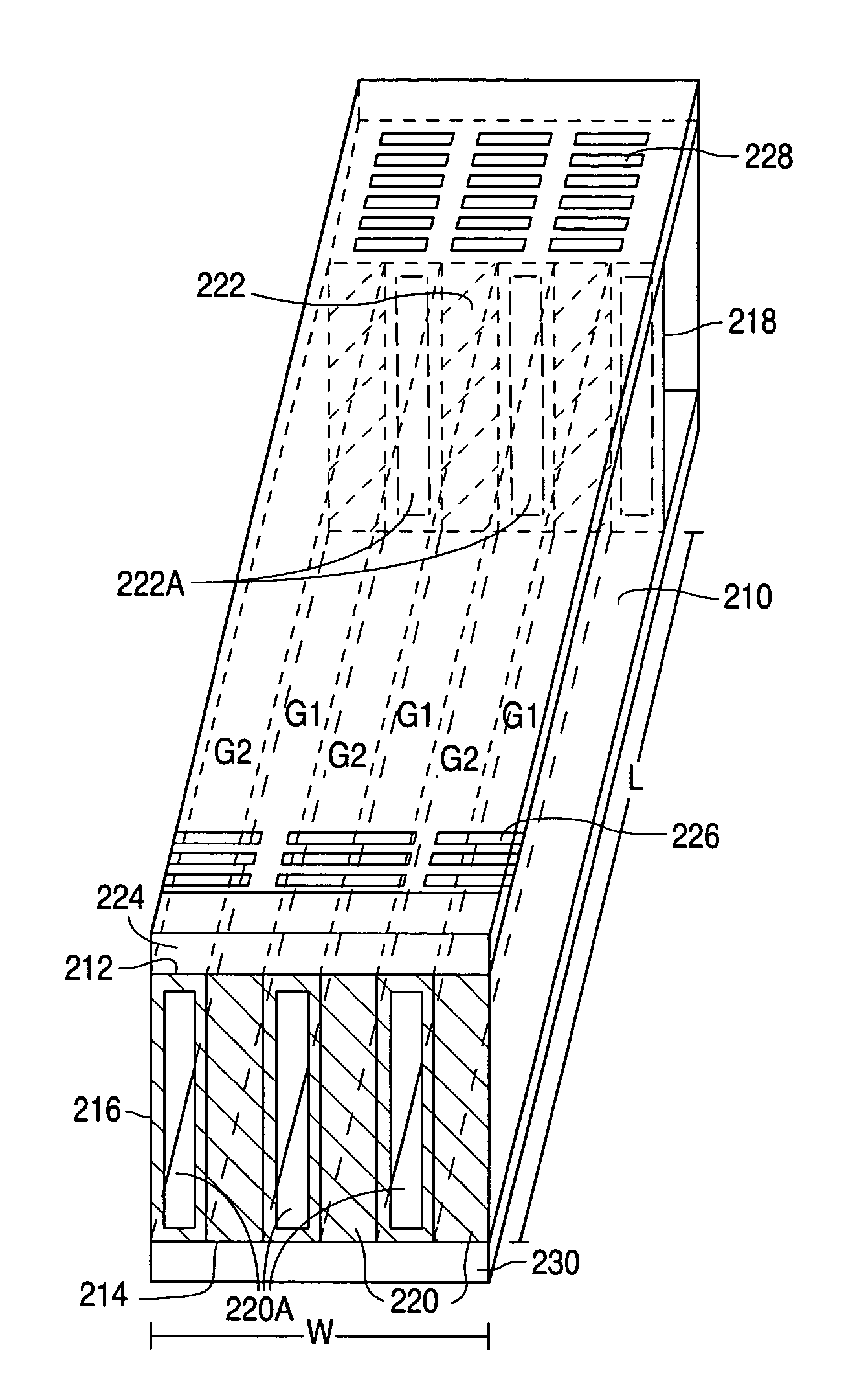
[0031]FIGS. 2A-2F show a series of views that illustrate an example of a heat exchanger 200 in accordance with the present invention. FIG. 2A shows a front side perspective view, while FIG. 2B shows a back side perspective view. FIG. 2C shows a top plan view taken between lines 2C1-2C1 and 2C2-2C2 of FIG. 2A, FIG. 2D shows a right side view taken along lines 2D-2D of FIG. 2C, and FIG. 2E shows a bottom plan view taken between lines 2E1-2E1 and 2E2-2E2 of FIG. 2B. FIG. 2F shows a perspective view of FIG. 2C taken along lines 2F-2F of FIG. 2C.

[0032] As shown in FIGS. 2A-2F, heat exchanger 200 includes an air flow structure 210 that directs the flow of external and internal air through heat exchanger 200. Air flow structure 210, in turn, has a top surface 212 and a bottom surface 214. In addition, structure 200 has a width W, a length L, a first edge 216 that runs along the width W, and a second edge 218 that runs along the width W.

[0033] Further, air flow structure 210 includes a nu...


PUM

PropertyMeasurementUnit
widthaaaaaaaaaa
lengthaaaaaaaaaa
adhesiveaaaaaaaaaa

Abstract

The efficiency of a heat exchanger is significantly improved by connecting walls to an air flow structure, which has first grooves formed in the top surface of the structure and second grooves formed in the bottom surface of the structure, that block off alternating ends of the first and second grooves such that a first air source can only flow through the first grooves and a second air source can only flow through the second grooves.

Description

BACKGROUND OF THE INVENTION [0001] 1. Field of the Invention [0002] The present invention relates to heat exchangers and, more particularly, to a heat exchanger with an increased heat transfer efficiency and a low-cost method of forming the heat exchanger. [0003] 2. Description of the Related Art [0004] Telecommunications equipment is commonly housed in electronics cabinets that sit outside in residential and commercial neighborhoods. The cabinets are water tight and air tight to prevent water and dust from entering the cabinets and reducing the useful life of the equipment inside the cabinets. [0005] When operating as intended, the telecommunications equipment produces heat which can damage the equipment when the heat inside the cabinet exceeds a predetermined temperature. To maintain an air tight enclosure and prevent the temperature from exceeding the predetermined temperature, electronics cabinets often use air-to-air heat exchangers. [0006]FIGS. 1A-1C show views that illustrate...

Claims


Application Information

Patent Timeline
Patent Type & Authority Applications(United States)
IPC IPC(8): F28D7/02
CPCF28D9/0025Y10T29/4935Y10S165/399H05K7/206
Inventor CALANNI, DANIEL J.GIACOMA, LAWRENCE M.
Owner TELLABS PETALUMA
Why Eureka
Try Eureka