
High voltage transformer

a high-voltage transformer and transformer technology, applied in the direction of transformer/inductance details, inductances, electrical devices, etc., can solve the problems of increasing the size and weight increasing the cost of fabrication of the transformer, and stray capacitance generated between the components of the high-voltage transformer, etc., to achieve the effect of less costly fabrication

Inactive Publication Date: 2008-08-26
POSKOM CO LTD
View PDF4 Cites 2 Cited by
  • Summary
  • Abstract
  • Description
  • Claims
  • Application Information

AI Technical Summary

Benefits of technology

"The present invention provides a small-sized, lightweight, and cost-effective high voltage transformer. It consists of two groups of components: a first group and a second group. Each group has a magnetic core part, a high voltage transforming part, a high voltage switch part, and a rectifying part. The components of the first group have a positive voltage change, while the components of the second group have a negative voltage change. The components of the first group are kept at the same potential distance from their first end, while the components of the second group are kept at the same potential distance from their first end. This ensures that the potential difference between the components of the first group and the components of the second group remains equal. The technical effect of this invention is to provide a compact, lightweight, and affordable high voltage transformer that can efficiently transfer electrical power."

Problems solved by technology

Even if the components of the high voltage transformer are electrically insulated by filling the insulating material or inserting the insulating bodies as noted above, it is impossible to completely eliminate the stray capacitance generated between the components of the high voltage transformer.
Such an increase in the distance between the components of the high voltage transformer leads to an increased size and weight of the high voltage transformer, thereby making the transformer costly to fabricate.

Method used


Image

  • High voltage transformer
  • High voltage transformer
  • High voltage transformer

Examples


Embodiment Construction

[0015]A high voltage transformer in accordance with the present invention will now be described in detail with reference to the accompanying drawings.

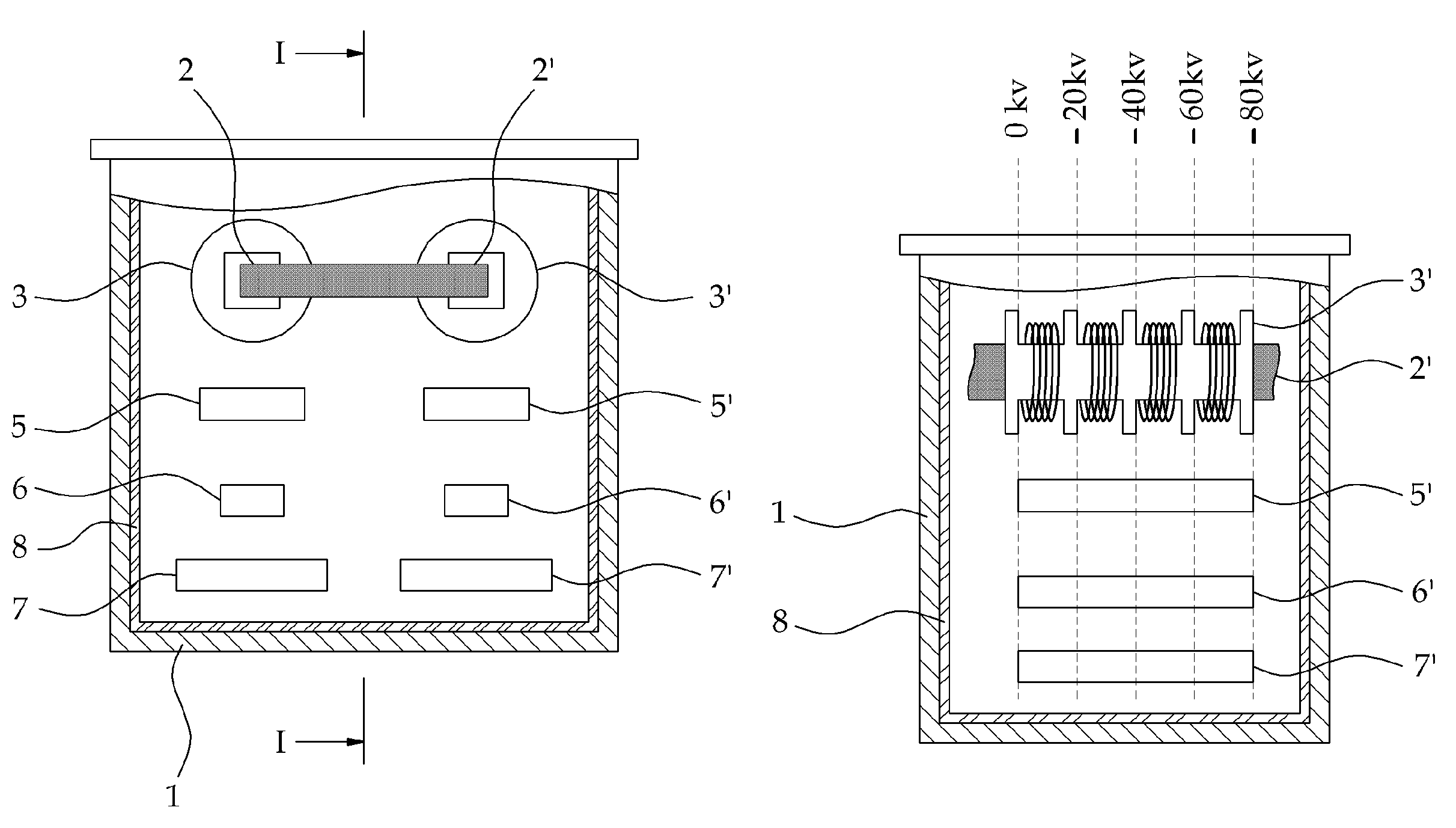
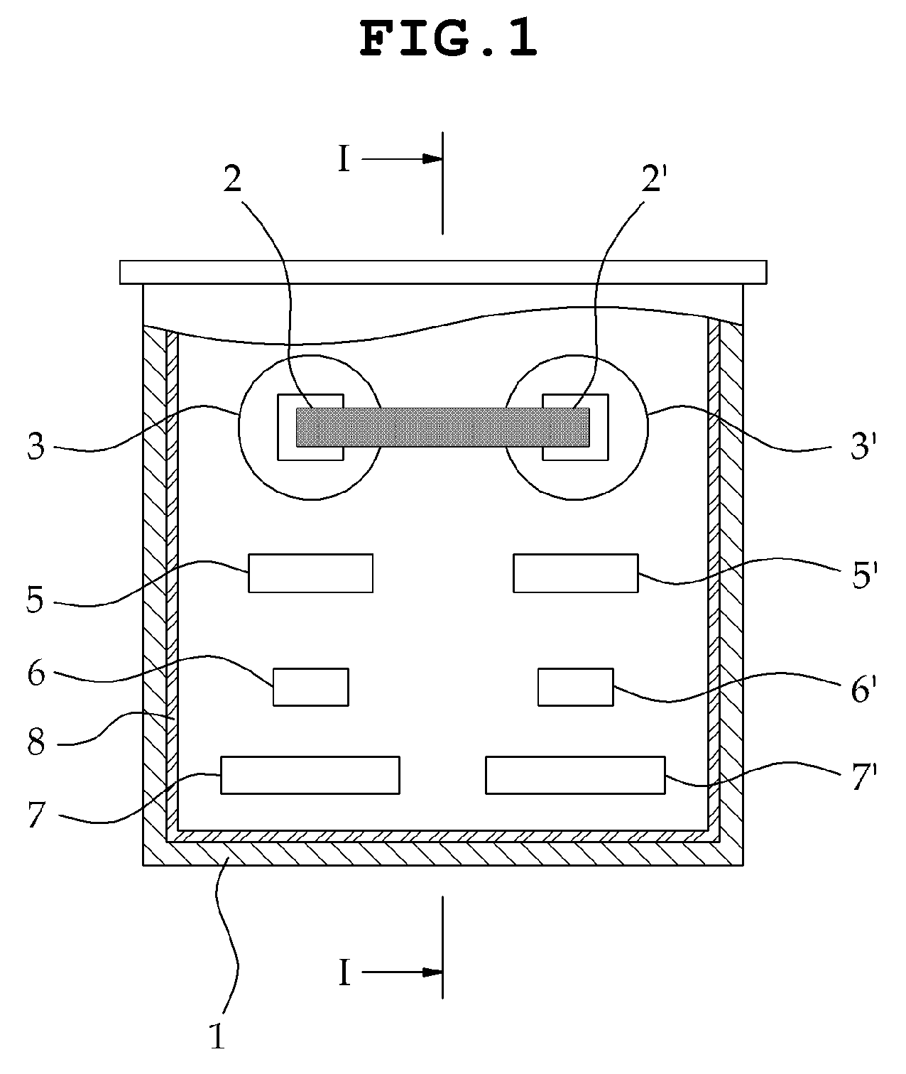
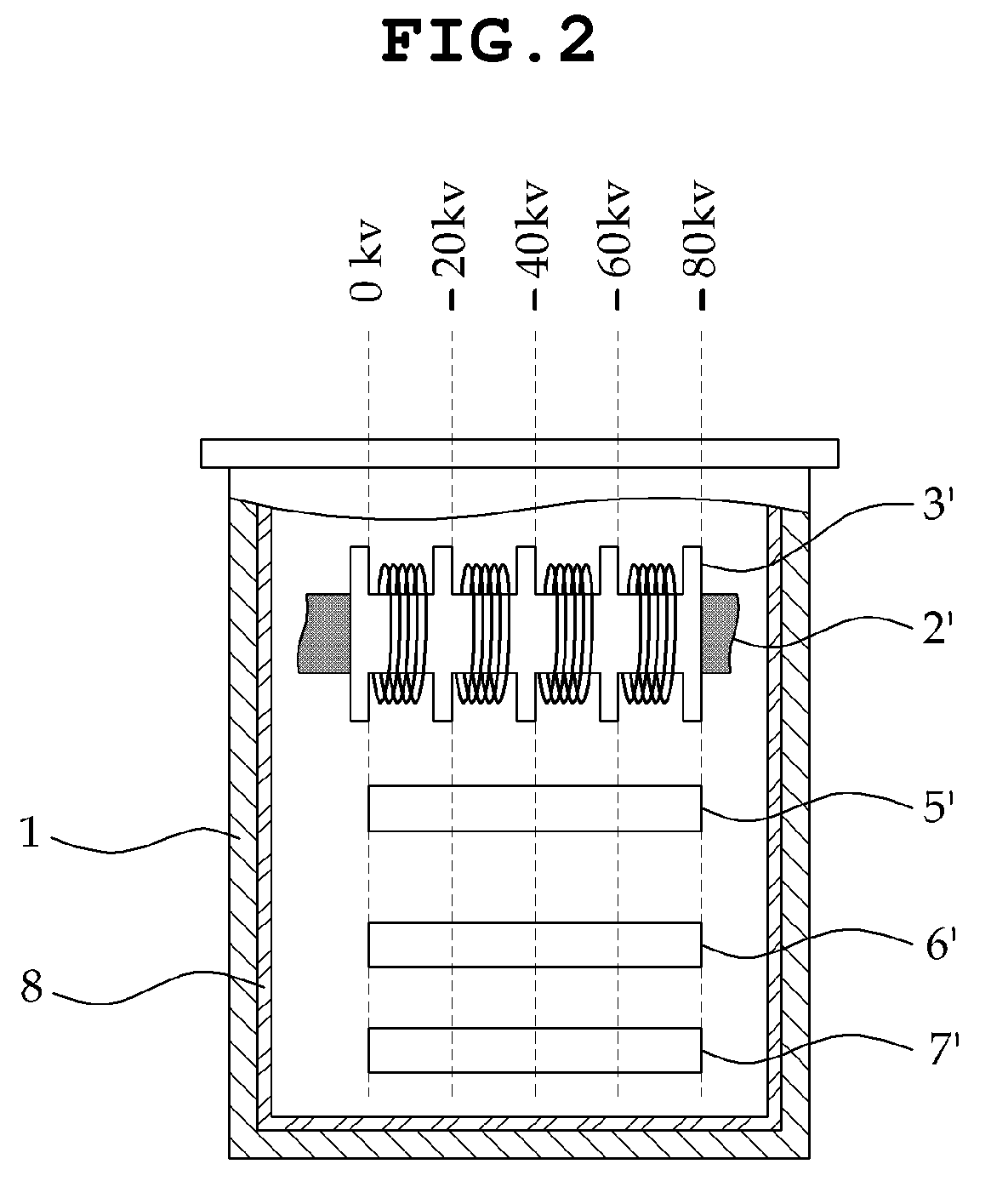
[0016]FIG. 1 is a top section view showing a high voltage transformer in accordance with one embodiment of the present invention. Referring to FIG. 1, a high voltage transformer includes a housing 1, magnetic core parts 2 and 2′, high voltage transforming parts 3 and 3′, rectifying parts including rectifying diodes 5 and 5′ and smoothing capacitors 6 and 6′, and anode and cathode high voltage switch parts 7 and 7′, all of which are received in the housing 1. The magnetic core parts 2 and 2′, the high voltage transforming parts 3 and 3′, the rectifying diodes 5 and 5′, the smoothing capacitors 6 and 6′ and the anode and cathode high voltage switch parts 7 and 7′ are divided into first and second transforming component groups.

[0017]The first transforming component group consists of the magnetic core part 2, the high voltage transforming ...


PUM

PropertyMeasurementUnit
voltageaaaaaaaaaa
distanceaaaaaaaaaa
sizeaaaaaaaaaa

Abstract

A high voltage transformer is small-sized, lightweight and less costly to fabricate. The high voltage transformer is designed to maintain equal the potential difference between the components of two transforming component groups and also to keep the components of the respective transforming component groups equipotential at the same distance in the direction extending from a first end to a second end. This eliminates the need to dispose an insulating body between the components of the first and second transforming component groups. This also makes it possible to fabricate the high voltage transformer with a small size and in a cost-effective manner.

Description

CROSS-REFERENCE TO RELATED PATENT APPLICATION[0001]This application claims the benefit of Korean Patent Application No. 10-2006-103603, filed on Oct. 24, 2006, in the Korean Intellectual Property Office, the disclosure of which is incorporated herein in its entirety by reference.FIELD OF THE INVENTION[0002]The present invention relates to a high voltage transformer and, more particularly, to a high voltage transformer that can be fabricated with a small size and in a cost-effective manner, while minimizing stray capacitance generated between components of the high voltage transformer.BACKGROUND OF THE INVENTION[0003]A conventional high voltage transformer includes a magnetic core, a high voltage transforming part provided with a low voltage bobbin and a high voltage bobbin surrounding the magnetic core, a rectifying part for rectifying a high voltage current induced in the high voltage bobbin and then smoothing the rectified high voltage current, and a high voltage switch part. One ...

Claims


Application Information

Patent Timeline
Patent Type & Authority Patents(United States)
IPC IPC(8): H01F27/28
CPCH01F38/16H01F30/06H01F27/34H01F27/40
Inventor SUNG, KI-BONGPARK, JONG-LAE
Owner POSKOM CO LTD
Learn More