Exothermic reaction system

a technology of exothermic reaction and cooler, which is applied in the direction of lighting and heating apparatus, chemical equipment and processes, organic chemistry, etc., can solve problems such as purification, and achieve the effect of rapid cooling of reaction gases and less costly fabrication and operation

Inactive Publication Date: 2010-04-20
SD LIZENZVERWGMBH
View PDF19 Cites 1 Cited by
  • Summary
  • Abstract
  • Description
  • Claims
  • Application Information

AI Technical Summary

Benefits of technology

[0011]In accordance with the present invention an improved reactor and cooler assembly is provided which is less costly to fabricate and operate, and which provides for rapid cooling of reaction gases. A tubular reactor of a conventional type is provided in conjunction with a heat exchanger which is integral with the discharge head of the tubular reactor and adapted to cool reaction gases.

Problems solved by technology

It is important that the reaction gas mixtures be rapidly cooled after completion of the desired reaction in order to minimize the possibility of complete oxidation as well as undesirable side reactions such as formation of formaldehyde and / or acetaldehyde; the formation of such products causes purification problems since they are difficult to separate from product ethylene oxide.

Method used


Image

  • Exothermic reaction system

Examples


Embodiment Construction

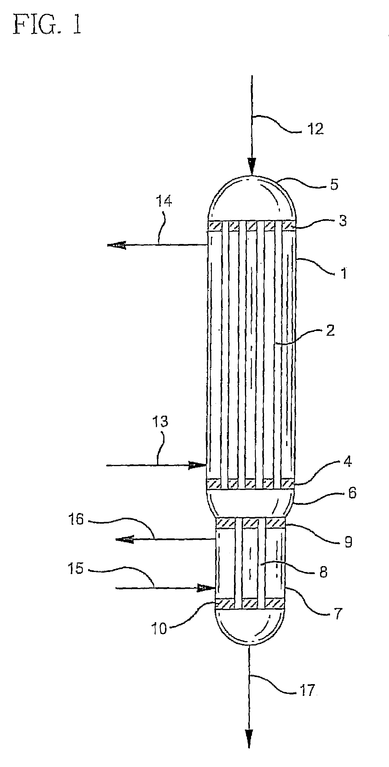
[0013]Referring to the drawing, reactor 1 is a shell and tube reactor of the type which is conventionally employed for ethylene oxide production. A multiplicity of elongated tubes 2 are provided in the reactor, the inlet ends being affixed to tube sheet 3 and the outlet ends to tube sheet 4. Inlet reactor head 5 is provided as is exit reactor head 6.

[0014]Shell and tube heat exchanger 7 is affixed to and integral with the exit reactor head 6, an opening is provided in exit head 6 for communication with heat exchanger 7 and conveniently heat exchanger 7 is welded to the exit head 6 around the opening thus forming an integral structure with the reactor. Heat exchanger 7 is provided with tubes 8 which are affixed to tube sheets 9 and 10 as indicated. Heat exchanger exit head 11 is provided.

[0015]In practice, reaction gases, e.g., ethylene, oxygen and ballast gas are introduced into reactor I via line 12 and pass at reaction conditions through reactor tubes 2 which are packed with an ap...


PUM

PropertyMeasurementUnit
temperatureaaaaaaaaaa
diameteraaaaaaaaaa

Abstract

A reactor and heat exchanger assembly is provided with the heat exchanger integrally affixed to the reactor exit head and adapted to immediately cool reactor gases from the reactor.

Description

RELATED APPLICATIONS[0001]This application is a divisional application of U.S. Ser. No. 09 / 779,030, filed Feb. 8, 2001.BACKGROUND OF THE INVENTION[0002]1. Field of the Invention[0003]The present invention relates to a reactor and cooler assembly which is useful for conducting exothermic reactions such as the reaction of molecular oxygen and ethylene to form ethylene oxide.[0004]2. Description of the Prior Art[0005]The oxidation of ethylene to form ethylene oxide is conventionally carried out in a shell and tube reactor. An appropriate solid catalyst comprised of silver is placed in elongated tubes and the reaction gases are passed at reaction conditions into contact with the catalyst. A circulating fluid is provided on the shell side to remove heat generated by the exothermic reaction.[0006]It is important that the reaction gas mixtures be rapidly cooled after completion of the desired reaction in order to minimize the possibility of complete oxidation as well as undesirable side re...

Claims


Application Information

Patent Timeline
Patent Type & Authority Patents(United States)
IPC IPC(8): C07D301/10B01J8/00F28D7/00F28D7/16
CPCB01J8/048B01J8/0496B01J8/067F28D7/16C07D301/10F28D7/0066F28D7/0091B01J2208/00212B01J2208/0053B01J2208/00522
Inventor BILLIG, BARRYBARIA, BHUPENDRA RANIBHAI
Owner SD LIZENZVERWGMBH
Why Eureka
Try Eureka