Tool chuck with power take off feature

a tool chuck and feature technology, applied in the field of tool chucks, can solve the problems of operator inadvertent release of grounded condition, cumbersome chuck key operation, and other inconveniences, and achieve the effect of reducing the number of chucks

Inactive Publication Date: 2006-03-23
BLACK & DECKER INC
View PDF99 Cites 55 Cited by
  • Summary
  • Abstract
  • Description
  • Claims
  • Application Information

AI Technical Summary

Benefits of technology

[0012] The above and other features of the invention including various and novel details of construction and combinations of parts will now be more particularly described with reference to the accompanying drawings. It will be understood that the details

Problems solved by technology

For example, the conventional tool chuck requires cumbersome chuck key operations, chuck key retention, and other inconveniences.
Such manipulations may be difficult, especially when the operator at

Method used


Image

  • Tool chuck with power take off feature
  • Tool chuck with power take off feature
  • Tool chuck with power take off feature

Examples


Embodiment Construction

I. Example Embodiment Depicted in FIG. 1

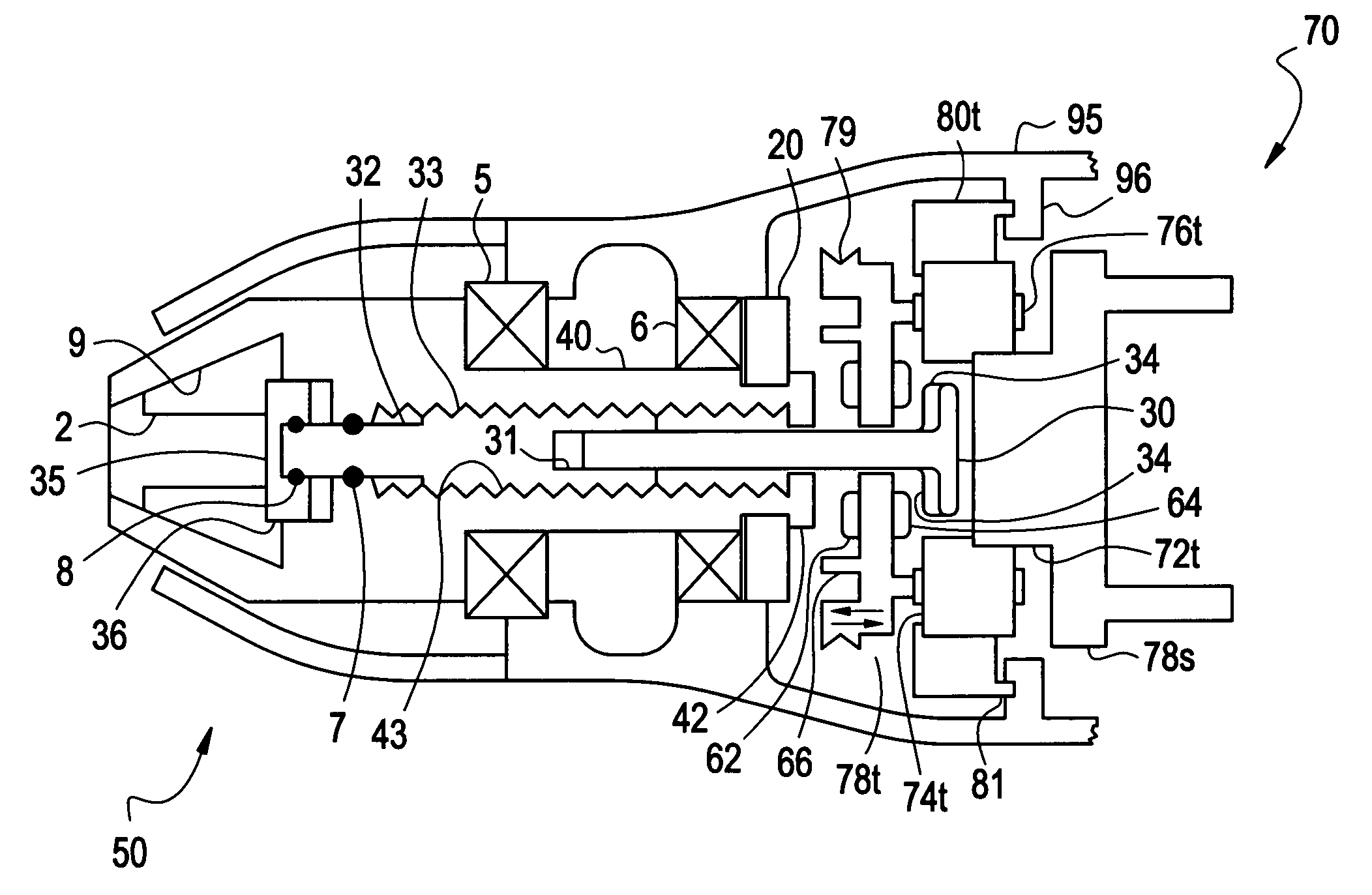
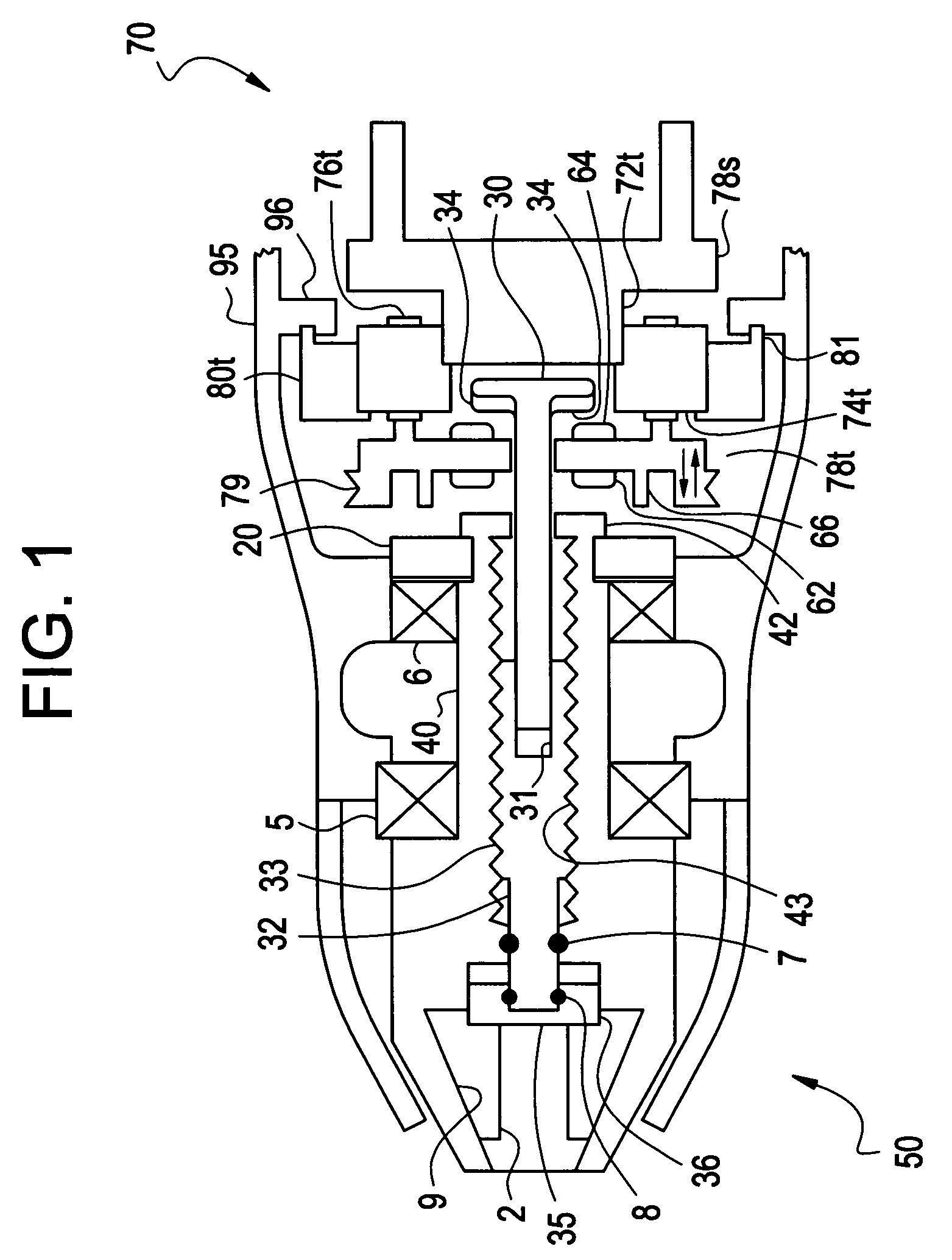
[0025]FIG. 1 shows an example, non-limiting embodiment of a tool chuck 50 with a power take off feature. The tool chuck 50 may be provided on a power driver (e.g., a drill) for holding a tool (e.g., a drill bit). It will be appreciated, however, that the tool chuck 50 may be suitably implemented on a variety of power drivers (other than drills) for holding a variety of tools (other than drill bits).

A. The Structure:

[0026] With reference to FIG. 1, the tool chuck 50 may be connected to the transmission 70 of a power driver. The transmission 70 may couple an electric motor (not shown) to the tool chuck 50. The transmission 70 may use gearing to effect a change in the ratio between an input rpm (from the electric motor) and an output rpm (delivered to the tool chuck 50).

[0027] In this example embodiment, the transmission 70 may include three planetary reduction systems. It will be appreciated, however, that the invention is not limited in thi...


PUM


Abstract

A tool chuck may include a shaft supporting chuck jaws. The shaft may provide a first transmission power path for rotationally driving the chuck jaws. The shaft may have a through hole. A chuck actuating mechanism may be provided in the through hole. The chuck actuating mechanism may provide a second transmission power path for opening and closing the chuck jaws.

Description

CROSS REFERENCE TO RELATED APPLICATIONS [0001] This US non-provisional application claims priority under 35 USC §119 to U.S. Provisional Application No. 60 / 610,973 filed Sep. 20, 2004, the content of which is incorporated herein in its entirety by reference.BACKGROUND [0002] 1. Field of the Invention [0003] The present invention relates in general to tool chucks for attachment of accessories to power drivers, and more particularly to a tool chuck having chuck jaws that may be actuated via power from the driver's transmission. [0004] 2. Description of Related Art [0005] Conventional tool chucks may have a turn ring that is rotatable using a chuck key to extend and retract chuck jaws. Although such tool chucks are generally thought to provide acceptable performance, they are not without shortcomings. For example, the conventional tool chuck requires cumbersome chuck key operations, chuck key retention, and other inconveniences. [0006] In view of the shortcomings associated with chuck ...

Claims


Application Information

Patent Timeline
IPC IPC(8): B23B31/12
CPCB23B31/1253B23B2231/06Y10T279/27Y10S279/902Y10T279/17615B23B2231/38
Inventor PUZIO, DANIELCOCHRAN, JOHN R.BUCK, JOHN E.
Owner BLACK & DECKER INC
Why Eureka
Try Eureka