Accessory drive mechanism for hybrid vehicle

a hybrid vehicle and drive mechanism technology, applied in the direction of transportation and packaging, instruments, etc., can solve the problems of engine b>1/b> consuming a large amount of traveling motor driving energy, inconvenient steering suddenly becoming heavy, resistance loss, etc., to avoid damage due to overload in the power transmission system m, tolerate the margin of error, and simple construction

Active Publication Date: 2012-10-25
NISSAN DIESEL MOTOR CO
View PDF29 Cites 57 Cited by
  • Summary
  • Abstract
  • Description
  • Claims
  • Application Information

AI Technical Summary

Benefits of technology

[0056]According to the present invention being constructed as mentioned above, since the accessory driving motor 12 is provided, the power steering pump 11A, the air compressor 11B, and the air-conditioner compressor 11C can be operated in a case that the hybrid vehicle travels by means of the traveling motor 8 alone, in other words, in a case that a power generated by an internal-combustion engine is not transmitted to travel the hybrid vehicle, in various kinds of facilities or commercial districts for example.
[0057]Furthermore, according to the present invention, by means of the first and second one-way clutches C1 and C2, it is possible to tolerate margins of error in switching timing upon switching between the power transmitted from the traveling drive system (D: side of the internal-combustion engine and / or the traveling motor) and the power transmitted from the accessory driving motor 12, in a simple construction.
[0058]Moreover, the power transmitted from the traveling drive system D and the power transmitted from the accessory driving motor 12 do not interfere with each other, and thereby, damage due to overload in the power transmitting system M can be prevent.
[0059]Here, it is sufficient for the accessory driving motor 12 to assure a number of revolutions slightly higher than the number of revolutions corresponding to low revolution N1, which is near an engine idling speed of the engine, in a case that the number of revolutions is converted to revolutions of the traveling drive system D, and therefore, an electric power consumed by the accessory driving motor 12 can be economized to the minimum level thereof.
[0060]As a result, according to the present invention, by means of simplifying the construction and the control process, a reliability of the mechanism is improved and an introduction cost is reduced.
[0061]Additionally, in the present invention, in a case that the signal indicating whether the air conditioner operates (the air-conditioner “ON / OFF” signal 53) can be input to the control device 50, a power required for driving the accessory for the air conditioner (the air-conditioner compressor 11C for compressing the refrigerant in the air conditioner), which accessory operates or stops irrespectively of a traveling condition, can be assuredly transmitted from the traveling drive system D or the accessory driving motor 12C for an air-conditioner.

Problems solved by technology

In the example of FIG. 20, since an accessory driving source is the engine 1, the accessory does not operate in a case that the engine 1 is stopped, and there is an inconvenience that steering suddenly becomes heavy occurs, for example.
However, in case that the traveling time is prolonged in which time the traveling motor 8 operates, resistance loss in an idling of the engine 1 consumes a large amount of traveling motor driving energy.
In the prior art in FIG. 22, although a construction is simple, in case that switching timing of a clutch 6a is inaccurate (the switching timing is messed up), it is highly possible that power interference of the traveling motor 8 and the accessory driving motor 12e is occurred, and that, the accessory driving motor 12e and / or a transmitting mechanism are damaged.
Furthermore, although operating conditions of a pump driving power steering (a power steering pump) and / or a compressor supplying compressed air (an air compressor) are greatly different from those of an air-conditioner compressor circulating a refrigerant in an air conditioner, such a difference in operating conditions is not taken into consideration and it is a problem.
However, since there are the double constructions in the accessory driving system thereof, there are problems that the constructions thereof are complicated and that an initial cost is expensive.
Therefore, since the accessory driving system has the double constructions as like as the prior art shown in FIG. 24, there are problems that the constructions thereof are complicated and that an initial cost is expensive.
Furthermore, it is not solved that operating conditions of the power steering pump and / or the air compressor are greatly different from those of the air-conditioner compression.
Therefore, there is not solution for problems that constructions thereof are complicated, the initial cost is expensive, and that operating conditions of the power steering pump and / or the air compressor are greatly different from those of the air-conditioner compressor.

Method used


Image

  • Accessory drive mechanism for hybrid vehicle
  • Accessory drive mechanism for hybrid vehicle
  • Accessory drive mechanism for hybrid vehicle

Examples


first embodiment

[0096]A description will be first given on a first embodiment with reference to FIG. 1 to FIG. 5.

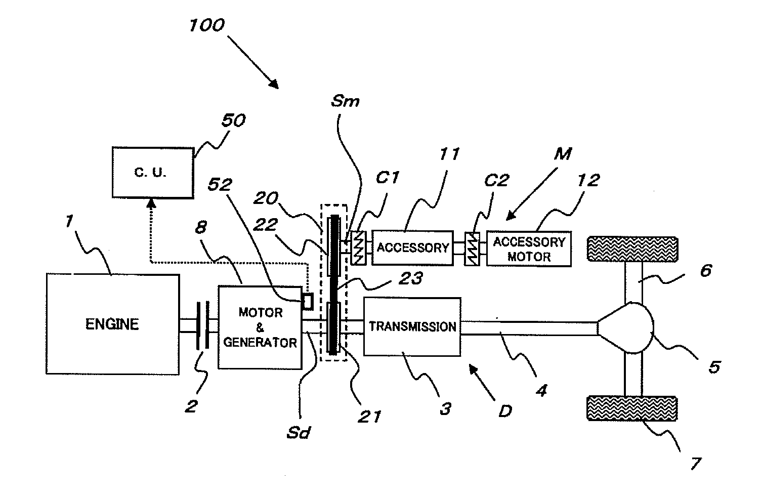
[0097]In FIG. 1, an accessory drive mechanism for a hybrid vehicle denoted by reference numeral 100 as a whole has an engine 1, a traveling drive system D, a drive power take-off mechanism 20, and an accessory system M.

[0098]The traveling drive system D has a clutch 2, a traveling motor which also serves as an electric generator (which will be referred to as a “traveling motor” hereinafter) 8, a transmission 3, a propeller shaft 4, a differential 5, a rear axle 6, and rear wheels 7. The traveling motor 8 operates as a motor at the time of start and operates as an electric generator at the time of deceleration.

[0099]The drive power take-off mechanism 20 is constructed by a first pulley 21, a second pulley 22, and a belt engaged with the two pulleys 21 and 22 in the example shown in FIG. 1.

[0100]The first pulley 21 is secured to a shaft Sd that connects the traveling motor 8 to the transmi...

second embodiment

[0159]A second embodiment will now be described with reference to FIG. 6 to FIG. 8.

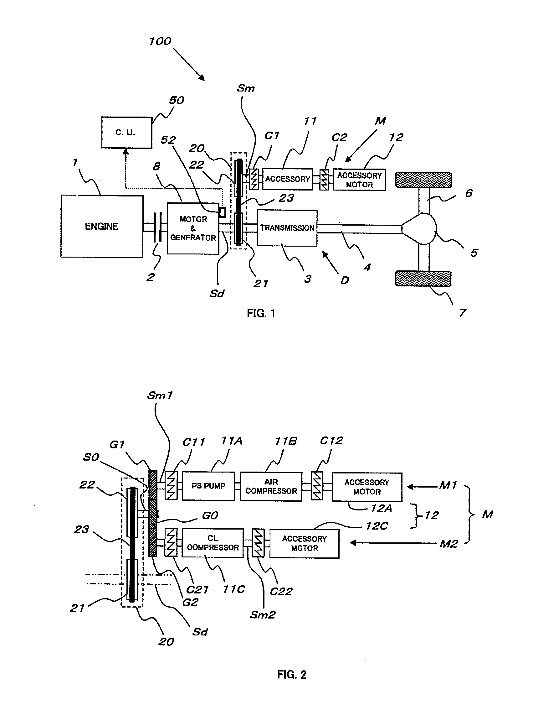
[0160]In the first embodiment, as shown in FIG. 2, the two divided accessory system M1 and M2 are provided with the accessory driving motors 12A and 12C, respectively.

[0161]On the other hand, in the second embodiment shown in FIG. 6, although an accessory system is divided into two systems M3 and M4, only one accessory driving motor (12A) is provided.

[0162]In FIG. 6, reference numeral 101 denotes an entire accessory drive mechanism according to the second embodiment. The accessory drive mechanism 101 has a drive power take-off mechanism 20, a power distribution mechanism 32, and the accessory systems M3 and M4.

[0163]A construction of the drive power take-off mechanism 20 is the same as that in the first embodiment.

[0164]A second pulley 22 of the drive power take-off mechanism 20 is secured to one end of a shaft group Sm3 of the accessory system M3. Further, the other end of the shaft group Sm3 is conn...

third embodiment

[0202]FIG. 9 shows a

[0203]In the second embodiment shown in FIG. 6, the drive power take-off mechanism 20, the one accessory driving motor 12A, and the power distribution mechanism 32 are used as the power source for accessory driving.

[0204]On the other hand, in the third embodiment depicted in FIG. 9, power distribution mechanism 34 and two accessory driving motors 12A and 12C are used as a power source for accessory driving.

[0205]The third embodiment will now be described hereinafter with reference to FIG. 9.

[0206]In FIG. 9, an accessory drive mechanism denoted by reference numeral 102 as a whole has a traveling drive system D, two accessory systems M1 (a first accessory system) and M2 (a second accessory system), and a power distribution mechanism 34.

[0207]The power distribution mechanism 34 includes three gears G5, G6, and G7.

[0208]The gear G5 is secured between a traveling motor 8 and a transmission 3 in the traveling drive system D.

[0209]Here, the power distribution mechanism ...


PUM


Abstract

An accessory drive mechanism for a hybrid vehicle, capable of operating accessories irrespective of the travel state of the vehicle, and also capable of smoothly switching between the power which is transmitted from the traveling motor side and the power which is transmitted from the accessory drive motor side. The accessory drive mechanism is provided with a drive power take-off mechanism (20) for taking out the power from a travel drive system (D). An accessory (11) is connected to the drive power take-off mechanism (20). A first one-way clutch (C1) which can transmit the power only to the accessory (11) side is disposed between the drive power take-off mechanism (20) and the accessory (11). An accessory driving motor (an auxiliary motor (12e)) is connected to the side of the accessory (11) which is on the opposite side from the drive power take-off mechanism (20). A second one-way clutch (C2) which can transmit the power only to the accessory (11) side is disposed between the accessory (11) and the accessory driving motor (12).

Description

TECHNICAL FIELD[0001]The present invention relates to a mechanism for driving various accessories in a hybrid vehicle (a hybrid electric vehicle) that may be traveled with driving force generated by an electric motor (a traveling motor) merely.BACKGROUND ART[0002]In a conventional vehicle 100J that is not a hybrid vehicle, as shown in FIG. 20, an accessory 11 is provided to an engine 11, and rotation of the engine 1 is used for driving the accessory 11 through a driving force transmitting mechanism 20.[0003]In FIG. 20, the rotation of the engine 1 of the vehicle 100J is transmitted to a clutch 2, a transmission 3, a propeller shaft 4, a differential gear 5, a rear axle 6, and rear wheels 7, as the above-mentioned order. In the example of FIG. 20, since an accessory driving source is the engine 1, the accessory does not operate in a case that the engine 1 is stopped, and there is an inconvenience that steering suddenly becomes heavy occurs, for example.[0004]Even in a hybrid vehicle,...

Claims


Application Information

Patent Timeline
Patent Type & Authority Applications(United States)
IPC IPC(8): F16H37/00F16H1/28G16Z99/00B60L50/16
CPCB60K6/383B60K6/48B60L11/14B60W10/30Y02T10/70Y02T10/6221Y02T10/7077B60L1/003B60W20/00B60L50/16Y02T10/62Y02T10/7072G16Z99/00B60W10/08
Inventor YAMADA, YOSHIAKITSUCHIYA, TAKAYUKIHIKIRI, KUNIHIKO
Owner NISSAN DIESEL MOTOR CO
Why Eureka
Try Eureka