Wind and water power generation device using a rail system

a technology of wind and water power generation and rail system, which is applied in the direction of electric generator control, machines/engines, mechanical equipment, etc., can solve the problems of insufficient prior art references in several respects, the mass of the vane/car assembly is expense of materials, and the inability to render the car derailment virtually impossibl

Inactive Publication Date: 2006-07-11
DAVISON FRED E +2
View PDF16 Cites 55 Cited by
  • Summary
  • Abstract
  • Description
  • Claims
  • Application Information

AI Technical Summary

Benefits of technology

[0011]There is, therefore, provided a power generation assembly for use in generating electrical power from air or water currents, and more particularly to a rail-based conveyance system having a low-mass car assembly. The assembly includes the following features. First, a rail system is provided. Slidably mounted on the rail is a car assembly. The car assembly includes a linkage portion that couples the car to a vane assembly. The vane assembly includes a frame, to which the linkage portion is connected, and at least one vane. A power-take-off device is pivotally coupled to the car. The power-take-off device engages generator drive wheels, which are coupled to a generator, thereby driving the generator.

Problems solved by technology

Further, all three suspension wheels are located inside the monorail, thereby rendering car derailment virtually impossible.
While the foregoing prior art references demonstrate improvement in the field of power generation, each of these prior art references have proven inadequate in several respects.
Additional concerns related to the mass of the vane / car assemblies are expense of materials.
For obvious reasons, the more materials that are required in constructing a power generation system, the more uneconomical the system becomes.

Method used


Image

  • Wind and water power generation device using a rail system
  • Wind and water power generation device using a rail system
  • Wind and water power generation device using a rail system

Examples


Embodiment Construction

)

[0035]The presently preferred embodiments of the invention will be best understood by reference to the drawings, wherein like parts are designated with like numerals throughout.

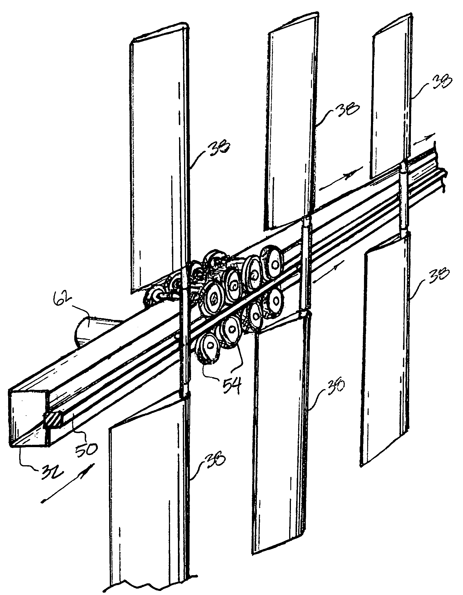
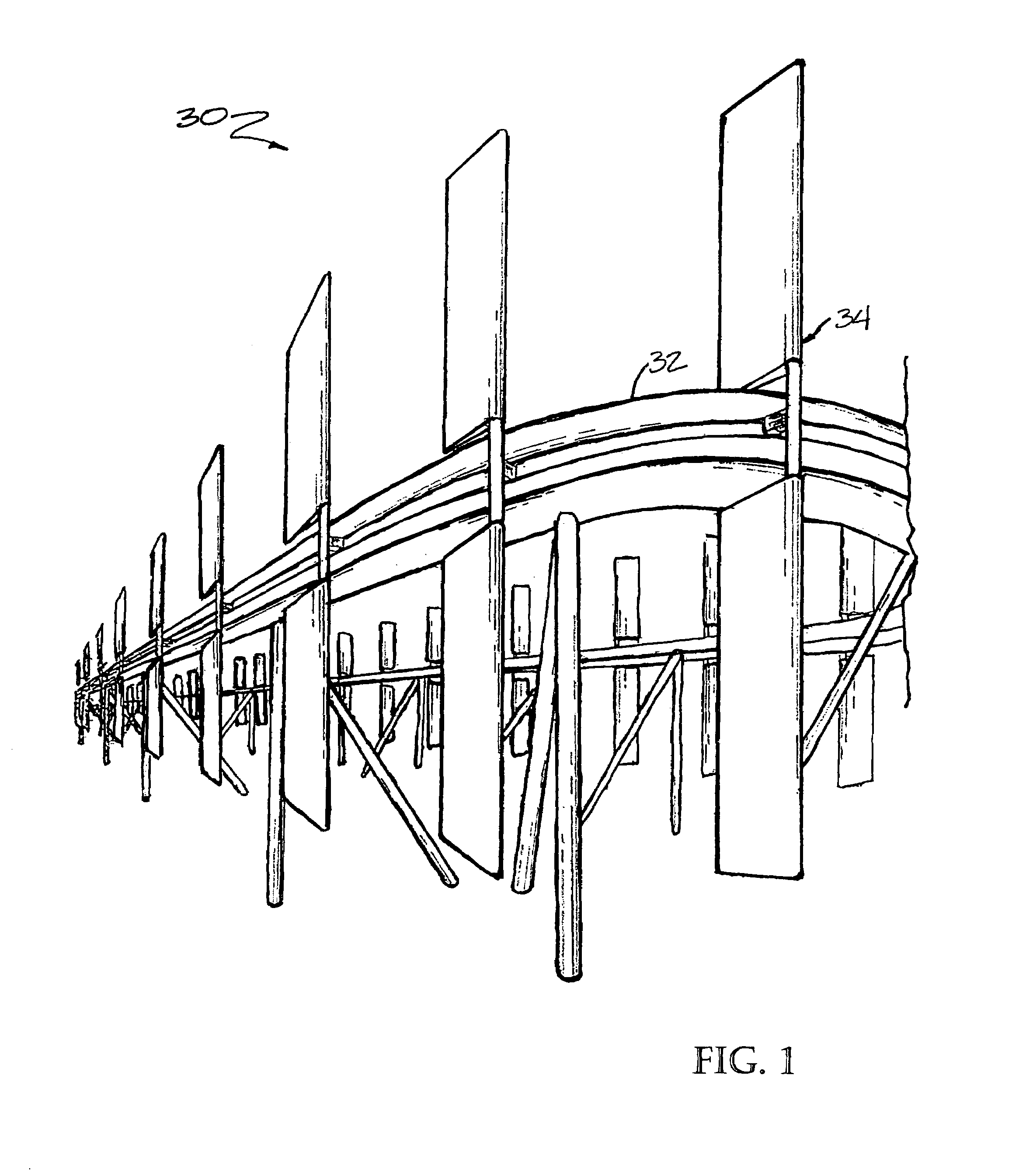
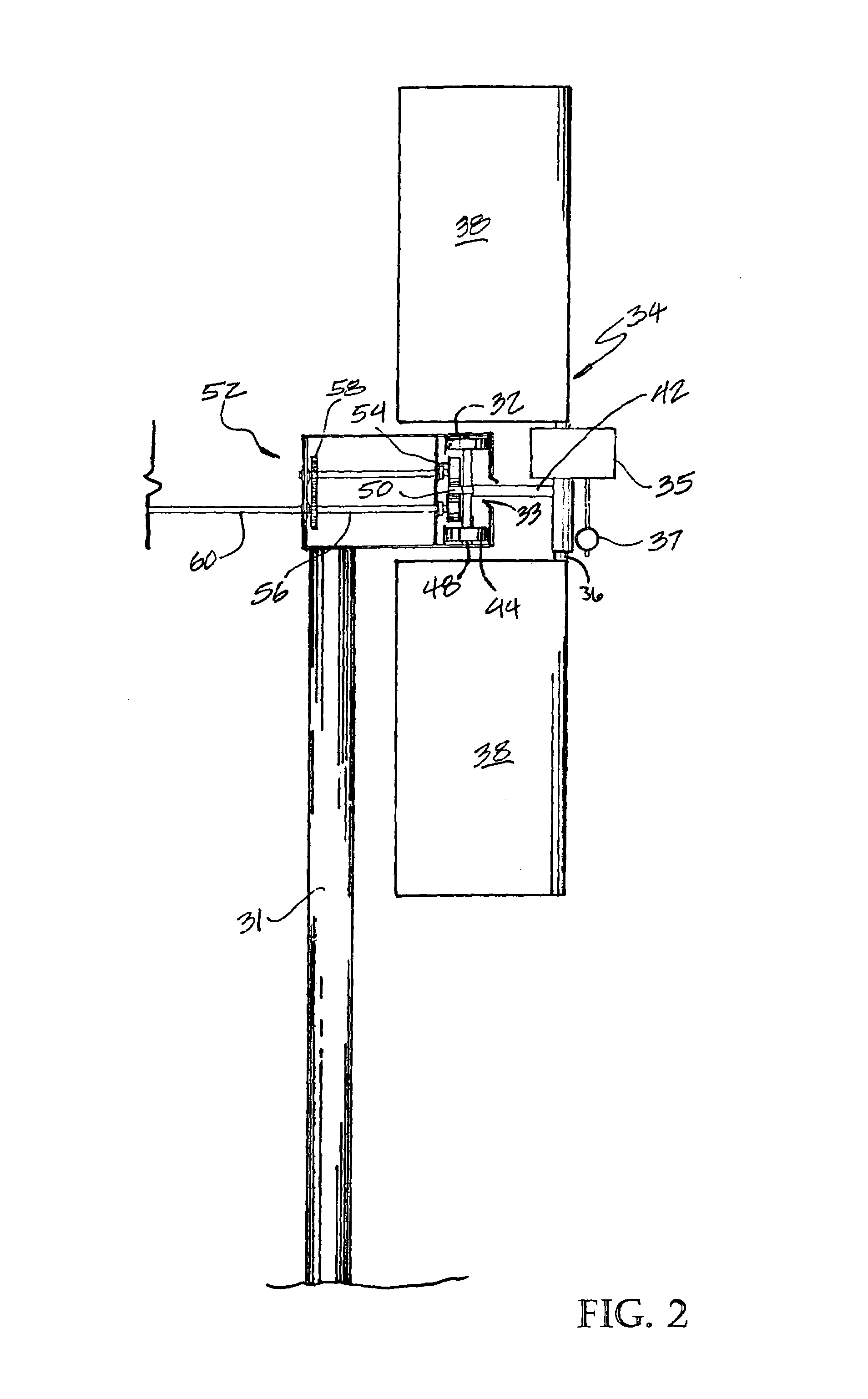
[0036]In FIGS. 1 and 2, a power generation assembly 30 is shown. The power generation assembly includes a rail 32, which in FIGS. 1 and 2, is a monorail supported by pole supports 31. In FIG. 1, numerous vane assemblies 34 are shown slidably mounted on the rail 32. However, it is noted that the actual number of vane assemblies 34 used in each power generation assembly 32 may vary depending on need.

[0037]The vane assembly 34 consists of a frame 36 and at least one vane 38 positioned on the frame 36. FIGS. 1 and 2, show both upwardly and downwardly deployed sails 38. The sails 38 are coupled to a common shaft 39 pivotal in a sleeve bearing 43 (FIG. 4), and are biased to one side so as to eliminate side to side movement within the rail 32. This biasing also keeps the guide wheels 44 turning in the same directio...


PUM


Abstract

A power generation assembly for use in generating electrical power from air or water currents includes a rail system forming a loop, a vane assembly having a frame and at least one vane, and a car assembly slidably mounted to the rail, including a linkage portion coupled to the frame of the vane assembly and a power-take-off arrangement includes an element that is operatively coupled to the car assembly and a drive wheel coupled to a generator and configured to take power off the moving car assembly by the drive wheels being rotated by the passing power take off element.

Description

RELATED APPLICATIONS[0001]This application claims priority from U.S. Provisional Application No. 60 / 215,794, filed on Jul. 5, 2000.THE FIELD OF THE INVENTION[0002]The present invention relates to a power generation assembly for use in generating electrical power from air or water currents, and more particularly to a rail-based conveyance system having a low-mass car assembly.BACKGROUND OF THE INVENTION[0003]For thousands of years, wind and water have been harnessed as sources of power. In Europe and Asia, for example, wind was a primary source of energy for thousands of years. More recently, much of the world's energy has been derived from fossil fuels. Because more energy could be more efficiently obtained from fossil fuels, they largely supplanted the use of wind and water as power sources. However, in a day where pollution, rising energy costs and depleting resources are among the chief concerns, harnessing water and wind as forms of energy is becoming more economically feasible ...

Claims


Application Information

Patent Timeline
Patent Type & Authority Patents(United States)
IPC IPC(8): F03B13/00F03B13/10F03D9/00H02P9/04F03B17/06F03D5/02F03D5/04
CPCF03B17/066F03D5/02F03D5/04Y02E10/70F05B2210/16Y02E10/28Y02E10/20
Inventor DAVISON, FRED E.
Owner DAVISON FRED E
Why Eureka
Try Eureka