
Concentrated buoyancy subsea pipeline apparatus and method

a technology of buoyancy and pipelines, applied in mechanical equipment, pipe laying and repair, pipe supports, etc., can solve the problems of pipelines crossing the ocean bottom to bend sharply, dangerous topographic features that can compromise pipelines and subsea structures, and complex topography

Active Publication Date: 2006-03-23
KELLOGG BROWN & ROOT INC
View PDF15 Cites 35 Cited by
  • Summary
  • Abstract
  • Description
  • Claims
  • Application Information

AI Technical Summary

Benefits of technology

This patent describes how to connect two parts of a pipeline through an underwater landform using buoyant devices that help keep them upright. These devices can be controlled by remote operators or left to settle naturally based on their weight. Fluids can also be used to adjust the buoyancy of the devices. Overall, this technique allows for more efficient connection between pipes without having to lay them out flat on the seabed.

Problems solved by technology

The technical problem addressed in this patent is how to safely allow subsea pipelines to navigate through complex topography without succumbing to bending, buckling, or collapsing due to sudden changes in slope caused by escarpments or other formations. Current methods for solving this issue involve either avoidance of certain areas or high costs and environmental damage.

Method used


Image

  • Concentrated buoyancy subsea pipeline apparatus and method
  • Concentrated buoyancy subsea pipeline apparatus and method
  • Concentrated buoyancy subsea pipeline apparatus and method

Examples


Embodiment Construction

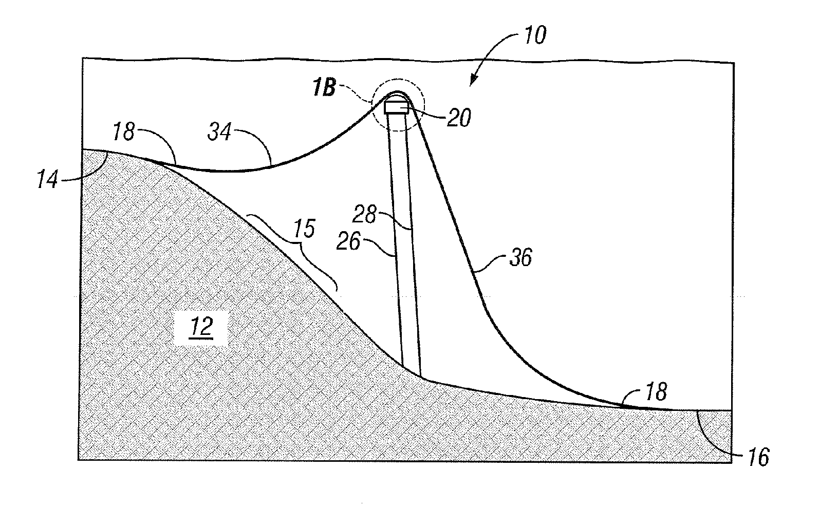
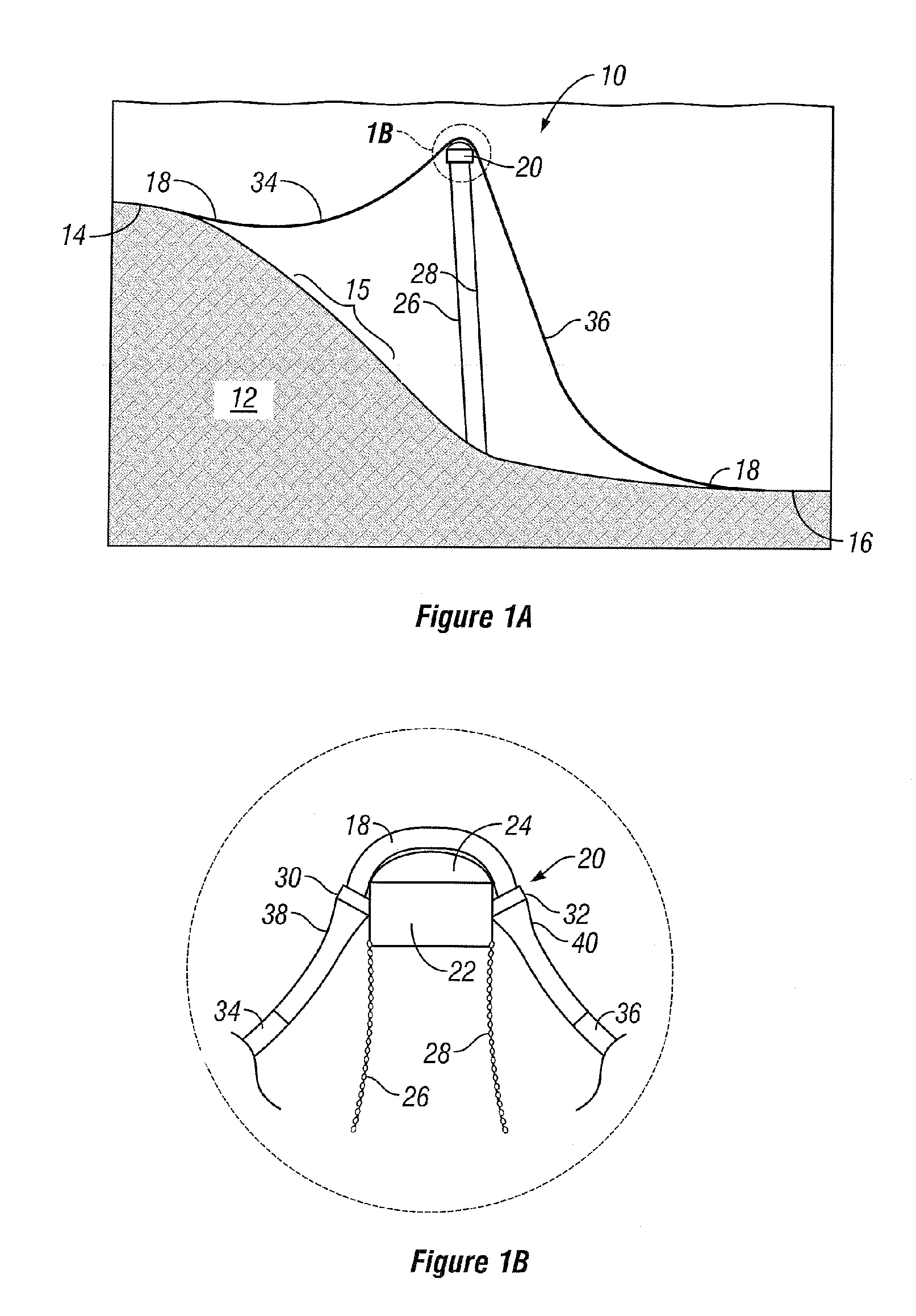
[0020] Referring initially to FIGS. 1A and 1B together, a schematic of a concentrated buoyancy pipeline system 10 is shown. System 10 is shown traversing an undersea scarp 12 and extends from the top 14 of scarp 12, across a slope 15, to a bottom 16 of scarp 12. System 10 includes a length of pipeline 18 in a bell-shaped configuration as it traverses scarp 12. While a scarp 12 is shown, it should be understood to one of ordinary skill in the art that various other topographic obstructions and hazards including, but not limited to, basins, domes, valleys, cliffs, and canyons, may be traversed without departing from the spirit of the invention.

[0021] To traverse scarp 12, a concentrated buoyancy assembly 20 is located approximately mid-span along pipeline 18 to make it positively buoyant. Buoyancy assembly 20 desirably includes a buoyancy device 22, a profiled surface 24, and one or more tethers or mooring lines 26, 28 to secure concentrated buoyancy assembly 20 in place. Optionally,...


PUM


Abstract

Various apparatuses and methods to traverse an undersea topographic feature (12) with a subsea pipeline (18) are disclosed. The apparatuses and methods of the present invention accomplish this task through the use of a concentrated buoyancy scheme (10). The invention disclosed can allow more efficient and cost effective traversal of hostile terrain for subsea pipelines at great depths while minimizing the risk of rupturing the pipeline (18) or negatively impacting the surrounding undersea environment.

Description


Claims


Application Information

Patent Timeline
Owner KELLOGG BROWN & ROOT INC
Learn More