
Method and system for a building database manipulator

Inactive Publication Date: 2004-04-13
EXTREME NETWORKS INC
View PDF118 Cites 145 Cited by
  • Summary
  • Abstract
  • Description
  • Claims
  • Application Information

AI Technical Summary

Problems solved by technology

As wireless communications use increases, radio frequency (RF) coverage within buildings and signal penetration into buildings from outside transmitting sources has quickly become an important design issue for wireless engineers who must design and deploy cellular telephone systems, paging systems, or new wireless systems and technologies such as personal communication networks or wireless local area networks.
A common problem for wireless systems is inadequate coverage, or a "dead zone," in a specific location, such as a conference room.
It is now understood that an indoor wireless PBX (private branch exchange) system or wireless local area network (WLAN) can be rendered useless by interference from nearby, similar systems.
The costs of in-building and microcell devices which provide wireless coverage within a 2 kilometer radius are diminishing, and the workload for RF engineers and technicians to install these on-premises systems is increasing sharply.
In practice, however, a pre-existing building or campus is designed only on paper and a database of parameters defining the environment does not readily exist.
It has been difficult, if not generally impossible, to gather this disparate information and manipulate the data for the purposes of planning and implementation of indoor and outdoor RF wireless communication systems, and each new environment requires tedious manual data formatting in order to run with computer generated wireless prediction models.
While the above papers describe a research comparison of measured vs. predicted signal coverage, the works do not demonstrate a systematic, repeatable and fast methodology for creating an environmental database, nor do they report a method for visualizing and placing various environmental objects that are required to model the propagation of RF signals in the deployment of a wireless system in that environment.

Method used


Image

  • Method and system for a building database manipulator
  • Method and system for a building database manipulator
  • Method and system for a building database manipulator

Examples


Embodiment Construction

The present invention is used to build databases for use with modeling and engineering planning and automated design products. The current embodiment permits repeatable, reproduceable computer representation that may be transported or exported into many standard file formats and is designed specifically for use with the SitePlanner suite of products available from Wireless Valley Communications, Inc. of Blacksburg, Va. However, it will be apparent to one skilled in the art that the method could be practiced with other products either now known or to be developed in the future. (SitePlanner is a trademark of Wireless Valley Communications, Inc.)

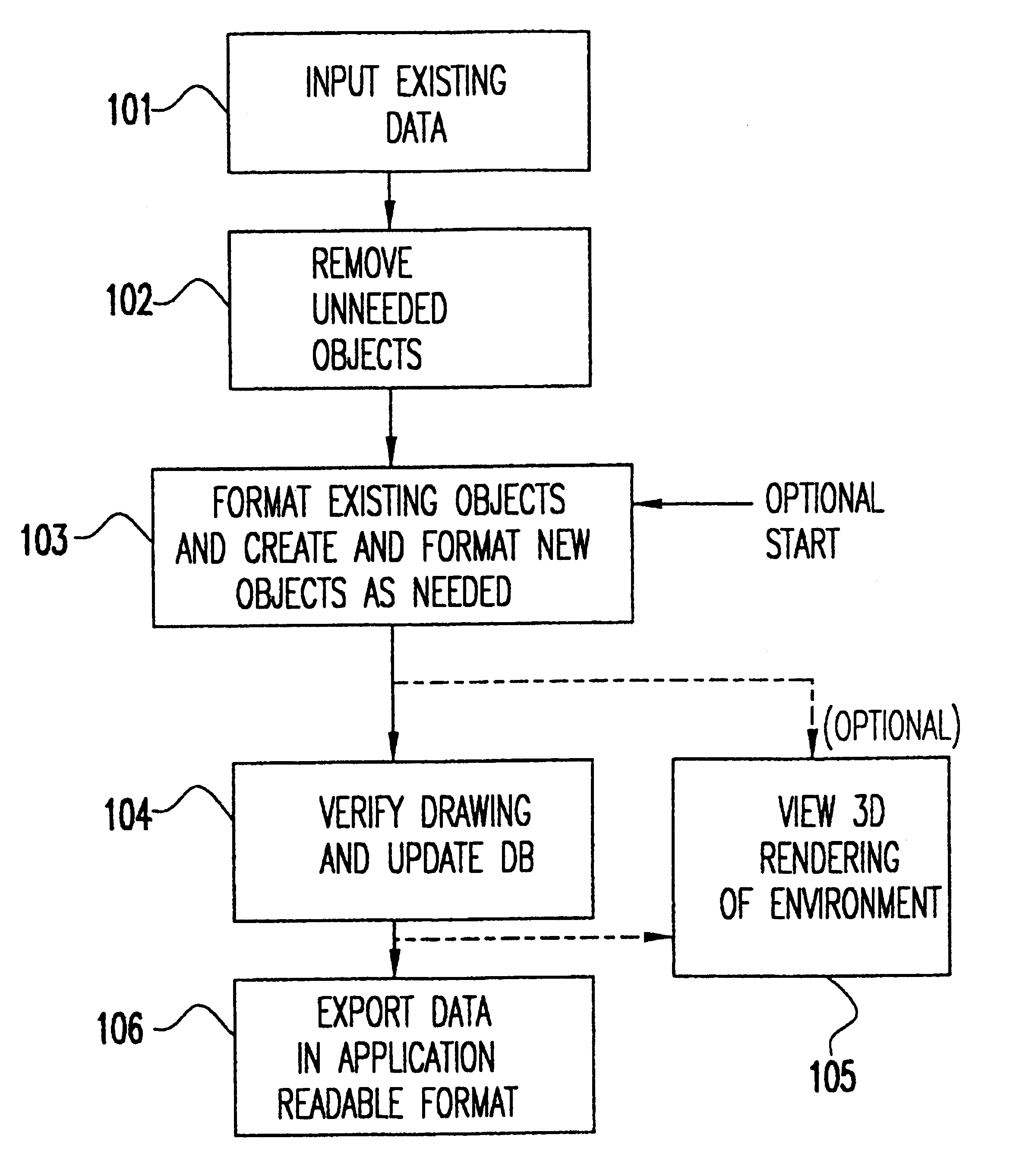
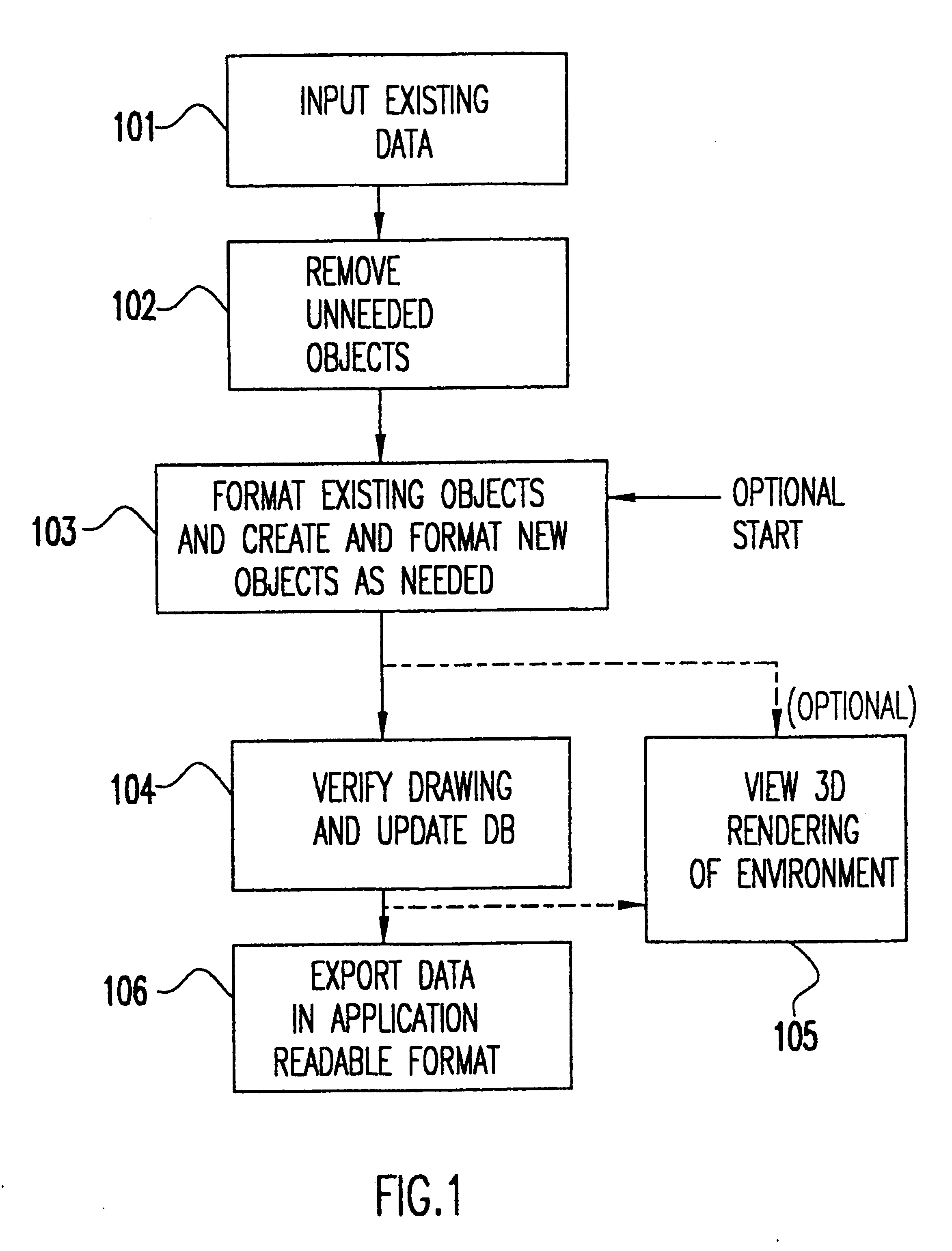
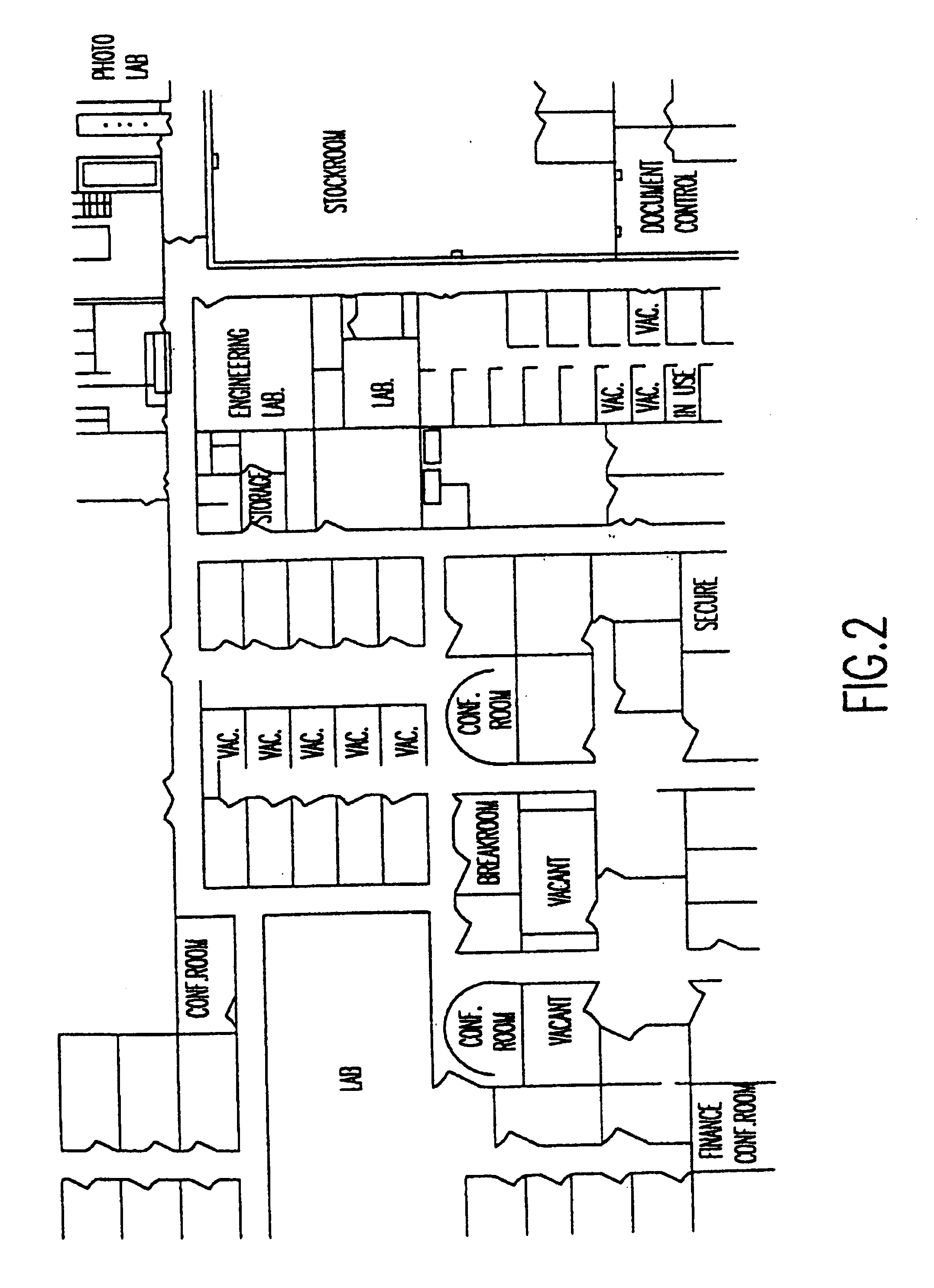
Referring now to the drawings, and more particularly to FIG. 1, there is shown a flow diagram for the method of the present invention. In order to build a specially formatted database that contains data necessary and sufficient for input into an engineering model, a definition of the desired environment must first be built. First, existing dat...


PUM


Abstract

A Building Databases Manipulator builds databases for a variety of physical environments including buildings, terrain, and other site parameters, by scanning in or rapidly tracing or editing data, and verifying that the data is formatted and sufficient for use in other engineering applications, and generating a set of formatted data which is transportable. Grouping objects in layers allows for simultaneous conversion of all objects in one layer to have certain predetermined attributes (e.g., converting objects to be made from glass versus cement; converting objects within a layer to have a uniform, smaller or larger, height or width dimension).

Description

DESCRIPTION1. Field of the InventionThe present invention generally relates to database development using computer aided design and, more particularly, to manipulating data from any environment in the world (e.g. cities, buildings, campuses, floors within a building, objects in an outdoor setting, etc.) to construct an electronic building database that can be used to generate definitions of the user's building and site parameters and used with wireless communication system modeling and engineering planning products.2. Background DescriptionAs wireless communications use increases, radio frequency (RF) coverage within buildings and signal penetration into buildings from outside transmitting sources has quickly become an important design issue for wireless engineers who must design and deploy cellular telephone systems, paging systems, or new wireless systems and technologies such as personal communication networks or wireless local area networks. Designers are frequently requested to...

Claims


Application Information

Patent Timeline
IPC IPC(8): G06F17/30
CPCG06F17/30244Y10S707/955Y10S707/99942Y10S707/99956Y10S707/959Y10S707/915Y10S707/922Y10S707/957Y10S707/921G06F16/50G06F30/13
Inventor RAPPAPORT, THEODORESKIDMORE, ROGER
Owner EXTREME NETWORKS INC
Learn More