Bicycle damping enhancement system

a technology for enhancing systems and bicycles, which is applied in the direction of shock absorbers, cycle equipment, cycles, etc., can solve the problems of inability to provide automatic adjustment of shock absorber settings, conventional shock absorbers configured with fixed damping rate, and used shock absorbers

Inactive Publication Date: 2006-01-31
SPECIALIZED BICYCLE COMPONENTS INC
View PDF38 Cites 147 Cited by
  • Summary
  • Abstract
  • Description
  • Claims
  • Application Information

AI Technical Summary

Benefits of technology

[0012]A bicycle shock absorber for differentiating between rider-induced forces and terrain-induced forces including a first fluid chamber having fluid contained therein. A piston is configured to compress the fluid within the fluid chamber. A second fluid chamber is coupled to the first fluid chamber by a fluid communication hose and an inertial valve is disposed within the second fluid chamber. The inertial valve is configured to open in response to terrain-induced forces and provides communication of fluid compressed by the piston from the first fluid chamber to the second fluid chamber. The inertial valve does not open in response to rider-induced forces and prevents communication of the fluid compressed by the piston from the first fluid chamber to the second fluid chamber.

Problems solved by technology

There are several problems associated with the conventional shock absorbers employed in the foregoing rear suspension systems.
One problem is that conventional shock absorbers are configured with a fixed damping rate.
However, there is no mechanism in the prior art which provides for automatic adjustment of the shock absorber setting based on different terrain and / or pedaling conditions.
A second, related problem with the prior art is that conventional shock absorbers are only capable of reacting to the relative movement between the bicycle chassis and the wheel.
In other words, the shock absorber itself has no way of differentiating between forces caused by the upward movement of the wheel (i.e., due to contact with the terrain) and forces caused by the downward movement of the chassis (i.e., due to movement of the rider's mass).

Method used


Image

  • Bicycle damping enhancement system
  • Bicycle damping enhancement system
  • Bicycle damping enhancement system

Examples


Embodiment Construction

[0025]A damping enhancement system is described which differentiates between upward forces produced by the contact of the bicycle wheel with the terrain and downward forces produced by the movement of the rider's mass. In the following description, for the purposes of explanation, numerous specific details are set forth in order to provide a thorough understanding of the present invention. It will be apparent, however, to one of ordinary skill in the art that the present invention may be practiced without some of these specific details. In other instances, certain well-known structures are illustrated and described in limited detail to avoid obscuring the underlying principles of the present invention.

An Embodiment of the Damper Enhancement System

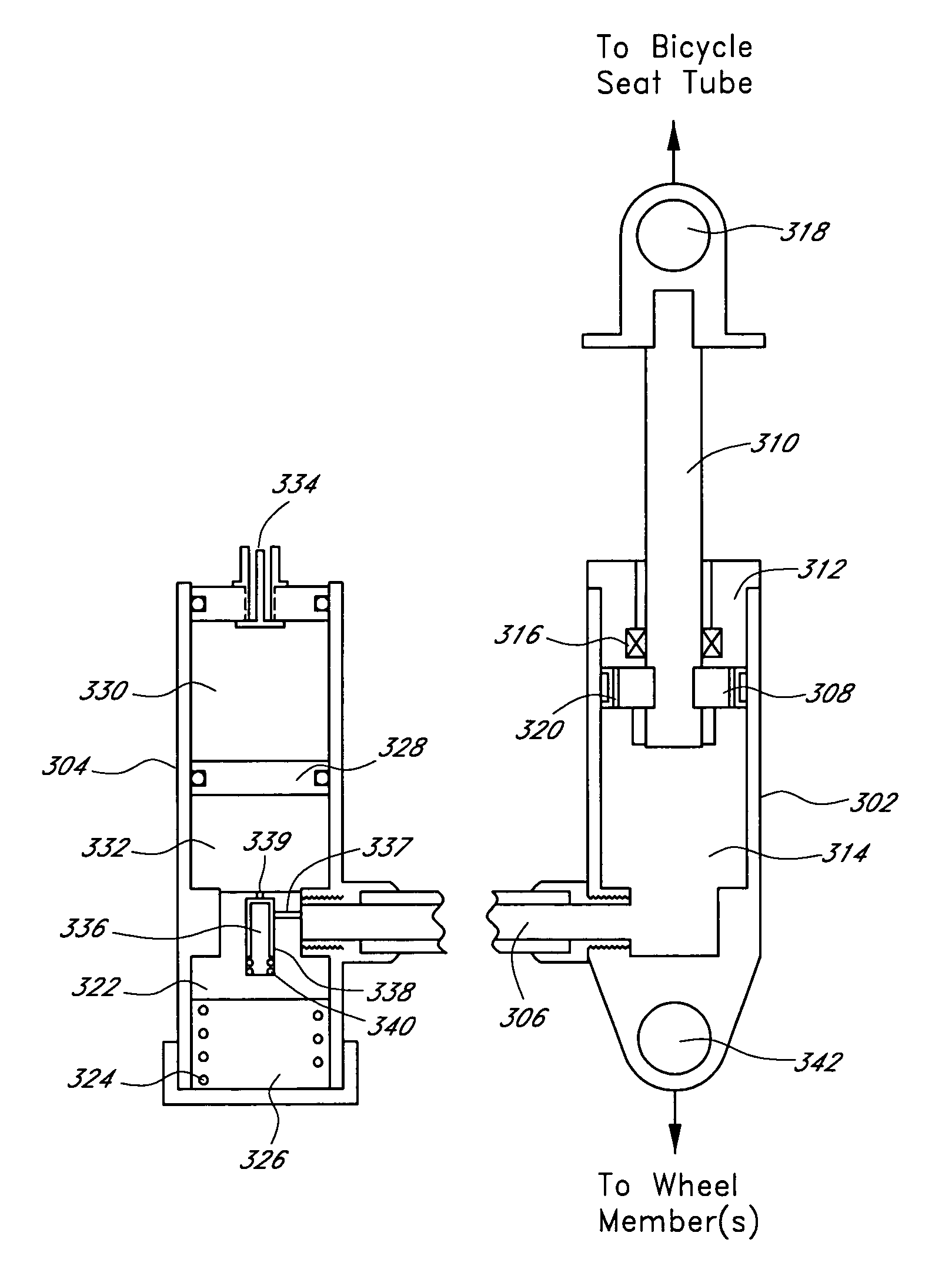
[0026]One embodiment of the present damper enhancement system is illustrated in FIG. 3. The apparatus is comprised generally of a primary tube 302 and a remote tube 304 coupled via a connector hose 306.

[0027]The damper enhancement system de...


PUM


Abstract

A bicycle shock absorber for differentiating between rider-induced forces and terrain-induced forces includes a first fluid chamber having fluid contained therein, a piston for compressing the fluid within the fluid chamber, a second fluid chamber coupled to the first fluid chamber by a fluid communication hose, and an inertial valve disposed within the second fluid chamber. The inertial valve opens in response to terrain-induced forces and provides communication of fluid compressed by the piston from the first fluid chamber to the second fluid chamber. The inertial valve does not open in response to rider-induced forces and prevents communication of the fluid compressed by the piston from the first fluid chamber to the second fluid chamber.

Description

RELATED APPLICATIONS[0001]This application is a continuation of U.S. patent application Ser. No. 09 / 919,582, filed Jul. 31, 2001 now U.S. Pat. No. 6,772,678, which is a continuation of U.S. patent application Ser. No. 09 / 288,003, filed Apr. 6, 1999, now U.S. Pat. No. 6,267,400.INCORPORATION BY REFERENCE[0002]The entireties of U.S. patent application Ser. No. 09 / 919,582, filed Jul. 31, 2001, and U.S. patent application Ser. No. 09 / 288,003, filed Apr. 6, 1999, are hereby expressly incorporated by reference herein and made a part of this specification.BACKGROUND OF THE INVENTION[0003]1. Field of the Invention[0004]This invention relates generally to the field of bicycle suspensions. More particularly, the invention relates to a damping enhancement system for a bicycle.[0005]2. Description of the Related Art[0006]For many years bicycles were constructed using exclusively rigid frame designs. These conventional bicycles relied on air-pressurized tires and a small amount of natural flexib...

Claims


Application Information

Patent Timeline
Patent Type & Authority Patents(United States)
IPC IPC(8): F16F9/34B62K25/04F16F9/096F16F9/504
CPCB62K25/04B62K25/286B62K25/10F16F9/504B62K3/02F16F9/096B62K2025/048B62K25/20
Inventor MCANDREWS, MICHAEL
Owner SPECIALIZED BICYCLE COMPONENTS INC
Why Eureka
Try Eureka