Virtual conference room

a virtual conference and video conferencing technology, applied in the field of virtual conference rooms, can solve the problems of inconvenient group interaction of individuals inability to see the reactions, body language or other activities of participants in the source room, and the television-to-television model of current video conferencing systems is not conducive to how individuals normally interact in the group setting. achieve the effect of overcompensating deficiencies and limitations and high fidelity resolution

Inactive Publication Date: 2006-10-10
DREAMWORKS ANIMATION LLC
View PDF34 Cites 96 Cited by
  • Summary
  • Abstract
  • Description
  • Claims
  • Application Information

AI Technical Summary

Benefits of technology

[0010]The present invention overcomes the deficiencies and limitations of conventional video conferencing by providing an enhanced video conferencing experience that provides the video conference participants located at different sites with the perception being in the same room visually as well as acoustically and permits the sharing of detailed images requiring high fidelity resolution. The virtual conference room results from the overall perception and impression of the participants being in a single shared space.
[0011]In one embodiment of the invention, two video conference rooms are provided in which each room includes a large format display system for displaying images from the other room and one or more cameras for capturing images from the room. The large format display system preferably spans most or all of one wall of the room. In each room, one of the cameras is situated at a location near the middle of the display system, with a mechanism for capturing an image at or about the anticipated eye level of the participants and oriented toward the conference room. Preferably, the location of each mechanism for capturing the image is such that the participants tend to look directly at such mechanism, or portion thereof, when looking at the large format display system. The location of the camera results in an image of the participants with the proper perspective and scale as if they were looking directly at the participants in the other room. This configuration has the effect that when the participants in one conference room look at an image of the other conference room displayed on the large format display system, they have the impression of looking directly into the other room, instead of looking at a conventional video conference monitor and cart. This perception creates the illusion of a shared physical space. To the participants in the other conference room, it appears that the other participants are looking directly at them, effectively making eye contact. This further enhances the illusion of shared space.
[0012]The large format display system further enhances the effect of the participants sharing a common physical space by presenting the images of the participants at or near “life size,” thereby enabling the participants to see facial expression, body language and other non-verbal cues at a realistic scale. Each room preferably has a high quality audio system to capture effectively the participants' voices and any other sounds in the room, and the video conference equipment is further preferably hidden to avoid any artificial obstacles in communication between the participants in the different conference rooms. For example, in one embodiment, the large format display system is built into an entire wall, the image is rear-projected on a display screen; the camera is also hidden behind the display screen and exposed through an aperture in the display. The aperture is positioned so its location corresponds to a portion of the image from the other room that is visually insignificant (i.e., showing a portion of the image from the other room that is not of interest to the participants). An example of visually insignificant content might be a control panel or object sitting near the center of the table. Because of the visually insignificant nature of the image of this object, the participants do not notice that they are looking at the camera when making eye contact with the participants in the other room.
[0013]In another embodiment, the camera may be located on or under the floor at a position corresponding approximately to the horizontal middle of the large format display system and adjacent to the large format display system, with the lens of the camera directed upward. In this embodiment, the large format display system does not have an aperture to receive the lens. Instead, the camera system uses a half mirror beam splitter that is positioned above the lens, at about or about the anticipated eye level of the participants and angled to project the image of the conference room and its participants on the camera lens. The half mirror beam splitter further permits the participants in the conference room to view through the half mirror beam splitter so as not to obstruct the view of the image projected on the display system behind the beam splitter. By taking steps to hide the video conferencing equipment, including camera, lens and projector, participants do not notice that they are being recorded, and do not feel “camera shy,” as is common with conventional video conferencing systems.
[0015]The result of using a video conference facility of the present invention is a virtual conference room, providing an enhanced video conferencing experience in which the participants feel as if they are immersed in a shared physical space and where visually and acoustically participants can feel as if they are directly looking at and speaking to each other including having eye contact with each other, discerning body language and other non-verbal cues and seeing detailed images from the other conference room.
[0016]The approach of the present invention is fundamentally different from the approach of conventional video conference systems. Conventional video conference products are complete, stand-alone systems for one room that make no assumptions about the physical layout, content or arrangement in the other room. The only assumptions made of the other room are to the video and audio standards (e.g., format, encoding, protocols, etc.), performance and bandwidth. In order to create a conventional end-to-end solution between two rooms, the conventional approach combines two complete stand-alone systems. The result limits the overall ability to create the illusion of shared physical space and to collaborate. In contrast, the present invention involves the overall design of both rooms including their physical layouts, contents and arrangements of items within the rooms. As such, the present invention is able to create the illusion of a shared physical space (including “eye-to-eye” contact among participants) and to hide the video conference equipment such as cameras.

Problems solved by technology

Conventional video conferencing facilities do not provide video conference participants located at different locations with the perception or feeling of being in the same physical space.
In particular, the viewers in the remote room cannot see the reactions, body language or other activity of the participants in the source room when the camera is zoomed in on only one of the participants there.
Further, the television-to-television model of current video conferencing systems is not at all conducive to how individuals normally interact in a group setting, such as in a group meeting.
The typical arrangement of a conventional video conference room all but makes realistic eye contact between individual participants impossible, and either overly exaggerates or suppresses body language and other non-verbal cues.
The result is a rather primitive form of video conferencing where participants rely primarily on voice and much less on useful visual information and cues in order to communicate and which thereby fails to convey much of the emotional content experienced with “in-person” meetings.
Further shortcoming of many conventional video conferencing systems include quite poor quality images, most often with low resolution due to bandwidth limitations, inability to properly handle simultaneous dialog, and improper lighting, and poor sound due to improper acoustics.
Moreover, the equipment of such conventional video conferencing systems can be obtrusive, with no effort made to hide the video conferencing equipment.
Because this equipment is so obtrusive, communication may be hindered because the participants feel like they are talking to a camera rather than another person and may be camera shy.
Furthermore, conventional video conferencing facilities are typically unable to capture and transmit images with high fidelity resolution.
Because conventional video conference facilities typically use a standard definition camera located at one remote end of a conference room for capturing an image of the entire room, they are unable to capture and transmit images within the conference room with high fidelity resolution.
Such conventional video conference systems are, at best, sufficient for capturing the rough outlines of participants in a conference room, but insufficient for capturing the details of a storyboard, lines of code, a CAD drawing, a schematic or any other detailed figures.
All of the above shortcomings substantially reduce the effectiveness of video conferencing as a way for remote individuals to collaborate, communicate and share ideas.

Method used


Image

  • Virtual conference room
  • Virtual conference room
  • Virtual conference room

Examples


Embodiment Construction

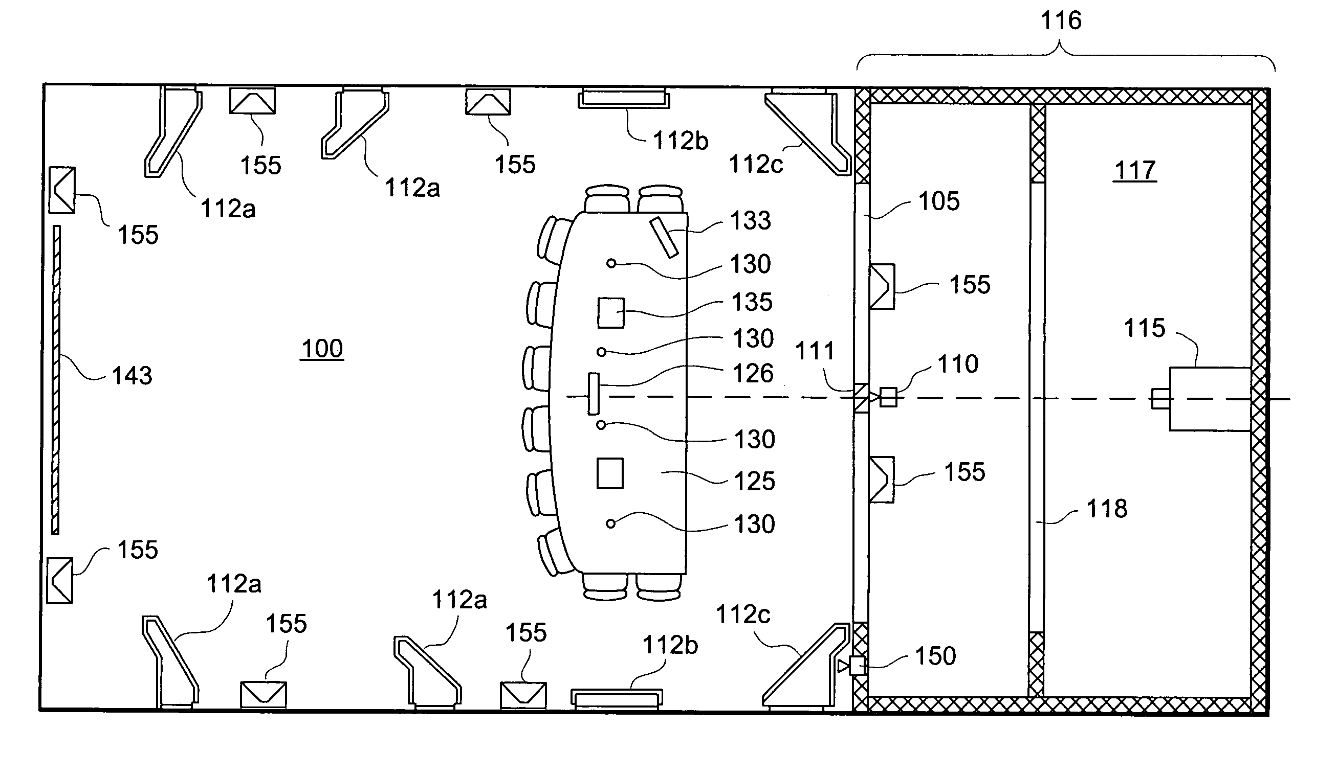
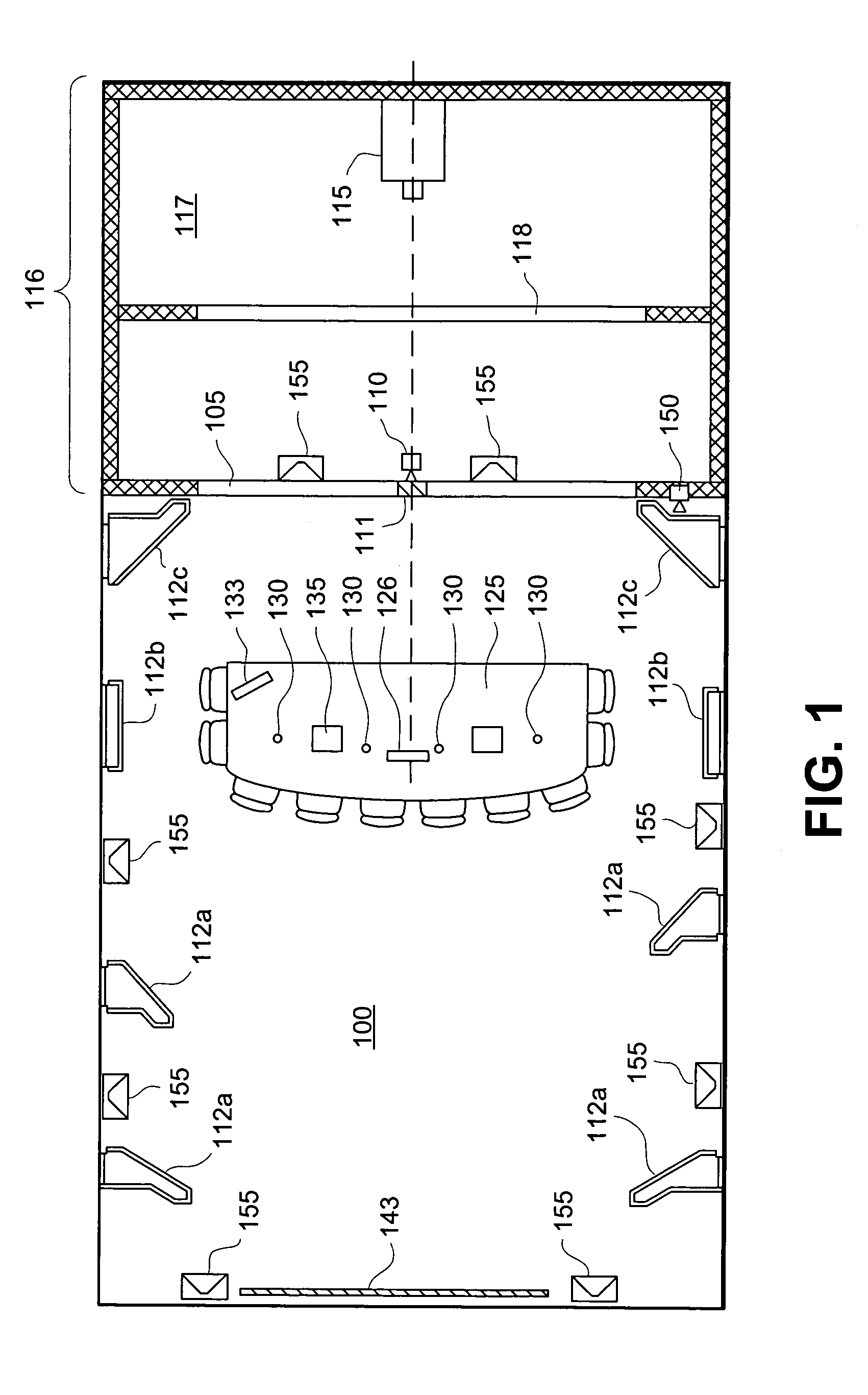
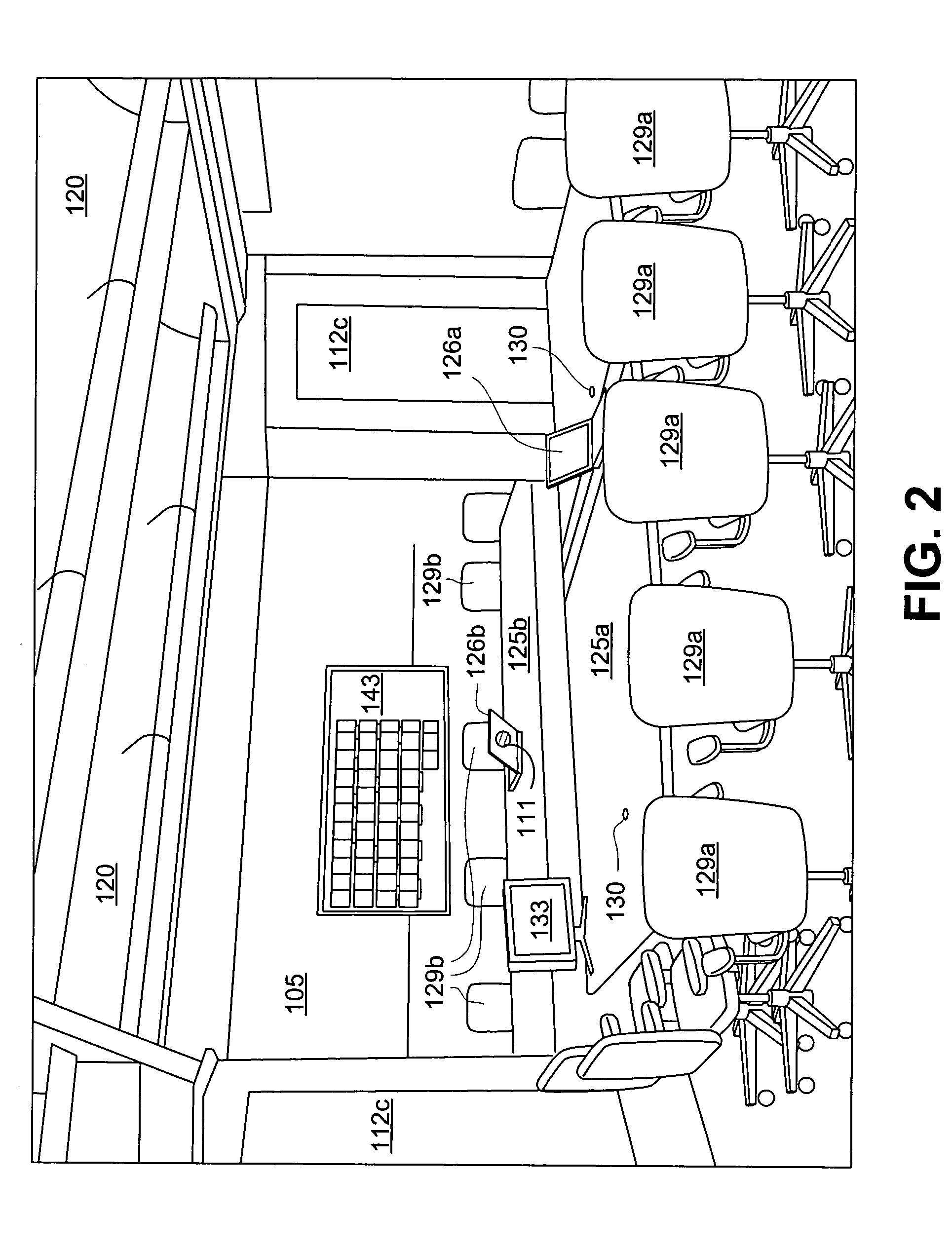
[0030]FIG. 1 illustrates a plan view and FIG. 2 provides a perspective view of a physical layout of a video conference room 100 in a first preferred embodiment. This video conference room 100 is electronically coupled over a network connection to another video conference room having substantially similar configuration to permit the transmission of images and sound between the conference rooms. This overall configuration of two conference rooms is shown in FIG. 3; the particular illustrated mirror-image orientation of the two rooms 100 is not a requirement of the invention since in fact the rooms are connected over a network, and their physical orientation to each other is irrelevant.

[0031]As shown in FIG. 1, this conference room 100 has a first camera 110 and a large format display system 116. The lens of the first camera 110 is directed toward the conference room 100 and its participants. The large format display system 116 includes a projection display device 115 for projecting an...


PUM


Abstract

An enhanced video conferencing system and method includes at least two conference rooms, the conference rooms connected together electronically to permit the transmission of images and sound from one room to the other room. Each room has a large format display system for projecting images and a camera positioned with respect to the large format display system to capture images of the conference room and its participants while the participants are looking at the large format display system, without obscuring the participants' view of the display system, so as to provide the perception that the participants in one conference room are looking directly at the participants in the other conference room. The enhanced video conferencing system may also include an additional camera for capturing an image of an item located at a pre-determined location within the conference room for ultimate transmission to the other conference room for viewing.

Description

BACKGROUND OF THE INVENTION[0001]1. Field of the Invention[0002]The present invention relates to video conferencing generally and, more particularly, to an enhanced video conferencing system and method that provides the illusion to the video conference participants located at different sites of being in the same physical space, such as being in the same room.[0003]2. Description of Background Art[0004]Conventional video conferencing facilities do not provide video conference participants located at different locations with the perception or feeling of being in the same physical space. Typically, a video conference system includes one or more standard definition cameras, and one or more television-sized monitors in each room. The cameras are located to capture an image of a view of an entire room (a source room) including its participants and to send the captured image to the video monitors in a destination room. The camera is typically located at one remote end of the source room, s...

Claims


Application Information

Patent Timeline
Patent Type & Authority Patents(United States)
IPC IPC(8): H04N7/14H04N7/15
CPCH04N7/142H04N7/15
Inventor LEONARD, EDWIN R.DAITCH, BRUCEFRANCISCO, EMMANUEL C.RUBIO, RICHARD F.CHAN, DEREKBESHEARS, JAMES F.
Owner DREAMWORKS ANIMATION LLC
Why Eureka
Try Eureka