Control system providing perspective flight guidance

a control system and flight guidance technology, applied in process control, navigation instruments, instruments, etc., can solve the problems of system operation, limited in the ability to display future flight path information, additional errors, etc., and achieve the effect of safe completion of the following/avoiding/tf/ta fligh

Inactive Publication Date: 2006-03-07
THE BOEING CO
View PDF12 Cites 144 Cited by
  • Summary
  • Abstract
  • Description
  • Claims
  • Application Information

AI Technical Summary

Benefits of technology

[0012]An aircraft guidance system of the present invention provides flight path vector (FPV) navigation using known terrain elevation data (e.g., calculated elevation data). Using pathway guidance cognitive processing, the workload required to safely complete terrain following / terrain avoidance (TF / TA) flight at low-altitudes (e.g., between 300-500 feet above ground level) is minimized.
[0013]In particular, a guidance system of the present invention attempts to prevent inadvertent flight into terrain and allows terrain-hugging flight to limit intervisibility using terrain elevation data contained within, for example, a digital map system, updated aircraft inertial track data from flight guidance computers and differential global positioning system (dGPS) navigation systems. This information is used in combination with generated perspective flight guidance symbology to enable a pilot to view visual representations of upcoming and lateral terrain.
[0014]The system provides a Perspective Flight Guidance (PFG) display that, in one embodiment, utilizes dGPS for waypoint geolocation, combined with a “quickened” predictive FPV symbol and “tunnel-in-the-sky” pathway guidance. The display enables pilots to anticipate avoidance flight requirements, thereby permitting the pilots to fly low to the ground (i.e., terrain flight) while avoiding obstacles (i.e., terrain avoidance) with increased accuracy, reduced intervisibility and reduced workload.

Problems solved by technology

Further, current generations of terrain flight guidance systems use radiated emissions and track errors displayed using compensatory tracking symbology (e.g., Delta-Veebar and Two-bar).
Such systems operate satisfactorily, but are limited in their ability to display future flight path information to the pilot and / or the results of pilot control input.
Thus, such displays cause much “mental gymnastics”, cognitive processing, and pilot mental workload, which may lead to additional error.
However, compensatory tracking symbology does not provide the pilot with information indicating how far the aircraft is off course or what flight control input is required to regain course centerline.
Furthermore, compensatory tracking does not provide flight path predictability, and displays that utilize compensatory symbology typically require more cognitive processing by the pilot.
This causes heavy pilot mental workload that may lead to errors, especially in high workload constrained terminal areas or during low altitude operations.
For example, excessive pilot mental workload can lead to full-scale deflection errors or total loss of situational awareness resulting in a maximum deviation mandated missed approach.
Thus, compensatory symbology often creates display clutter and high pilot cognitive workload, which increases the risk of flight technical errors (FTE's).
These systems, while accurate, are limited in that the display and data are restricted by the performance of the sensor system.
For example, turning limitations from the turn rate / bank angle limiter on some multi-mode radars precludes the system from “seeing” around or into the turn.
Further, and for example, current sensor-based systems cannot provide the pilot with reliable “nose over” cueing to enable terrain flight because the emitter sensor cannot “look over” the terrain ahead, but must rely on line-of-sight (LOS) operation.

Method used


Image

  • Control system providing perspective flight guidance
  • Control system providing perspective flight guidance
  • Control system providing perspective flight guidance

Examples


Embodiment Construction

[0034]The following description of the preferred embodiments is merely exemplary in nature and is in no way intended to limit the invention, its application, or uses. Although the present invention is described in connection with specific systems operating to provide particular displays using specific information, it is not so limited, and the present invention may be provided in connection with other systems providing different or additional displays using different information.

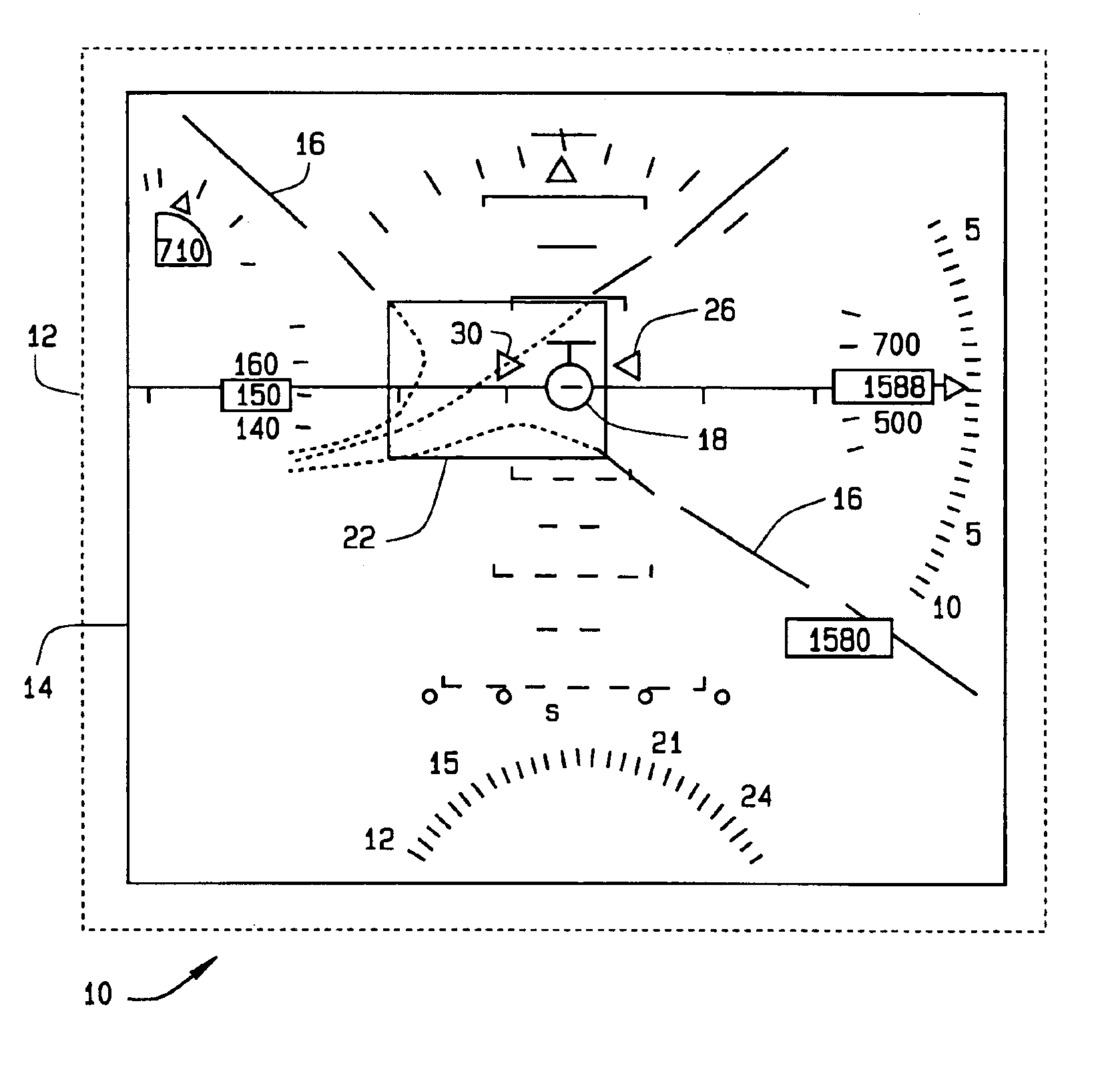
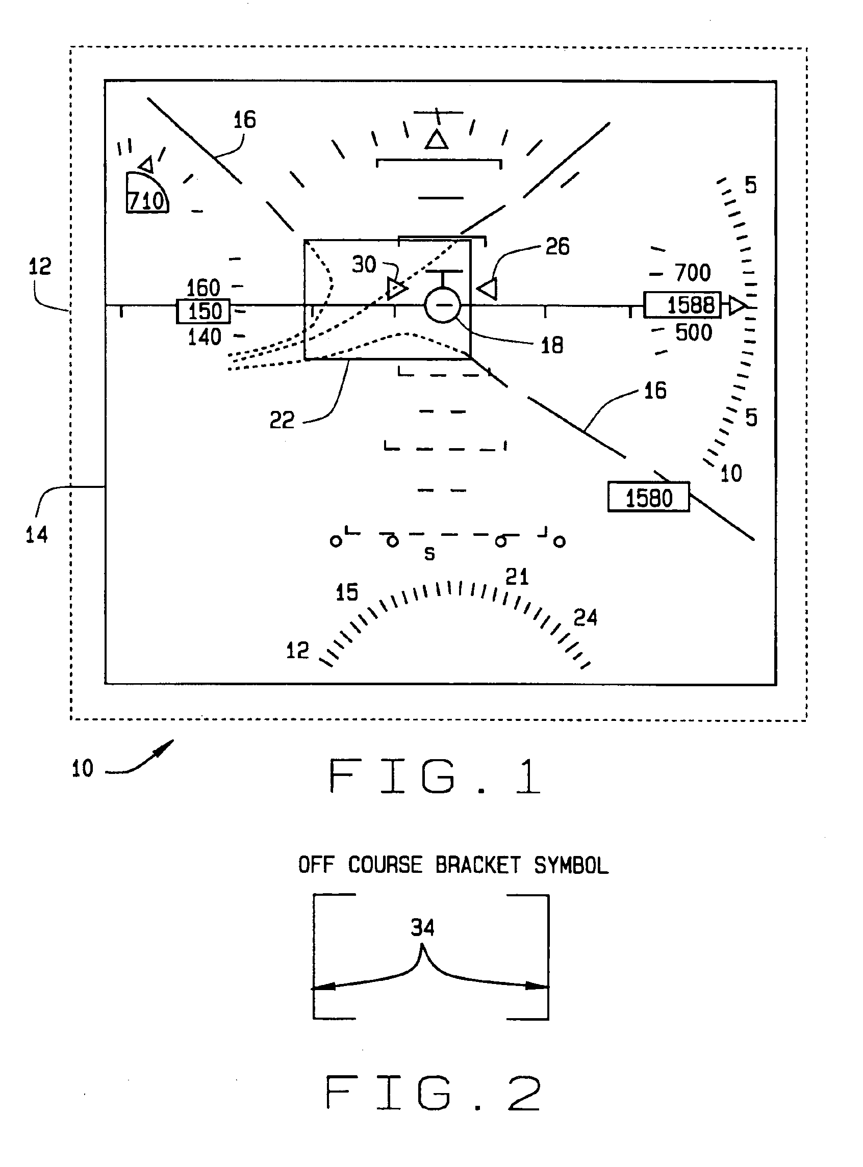
[0035]Referring to FIG. 1, a graphical representation of a predictive flight path symbology system 10 in accordance with an exemplary embodiment of the present invention is shown. The system 10 includes a flight path vector (FPV) based precision pathway flight guidance (PFG) symbology set 12 and a pilot display 14 on which the PFG symbology set 12 is displayed. The PFG symbology set 12 includes an open tunnel bounded by broken tunnel lines 16 that provides flow field data, such as, for example a Boeing Phila...


PUM


Abstract

A flight guidance system providing perspective flight guidance symbology using positioning and terrain information provides increased pilot situational awareness of the pilot's aircraft. The guidance system uses a positioning system and a detailed mapping system to provide a perspective display for use in an aircraft. A precision pathway flight guidance (PFG) symbology set is thereby displayed on a pilot display. The PFG symbology set includes broken line symbols representing an open tunnel and providing flow field data, a half-bracket symbol to indicate that the aircraft is no longer in the open tunnel represented by the broken line symbols and a quickened flight path vector (QFPV) symbol to provide the pilot with predictive flight path information. A flight director system and tunnel generator component provide for updating the displayed PDFG symbology set based upon current aircraft conditions (e.g., aircraft position) and stored flight path information.

Description

CROSS-REFERENCE TO RELATED APPLICATIONS[0001]This application is a continuation-in-part of U.S. patent application Ser. No. 09 / 975,624 filed Oct. 11, 2001 now U.S. Pat No. 6,798,423, and entitled “PRECISION PERSPECTIVE FLIGHT GUIDANCE SYMBOLOGY SYSTEM”, the entire disclosure of which is hereby incorporated herein by reference.STATEMENT REGARDING FEDERALLY SPONSORED RESEARCH[0002]The invention described herein was made in the performance of work under NRTC-RITA Cooperative Agreement No. NCCW-0076 WBS 00D-RITA-05-10-P2 and the U.S. Government may have certain rights thereto.FIELD OF THE INVENTION[0003]The present invention relates generally to aircraft guidance systems using perspective flight guidance information.BACKGROUND OF THE INVENTION[0004]In order to reduce tracking errors and pilot workload, a pilot may be provided with increased situational awareness of an aircraft with respect to a desired flight path. In particular, a pilot must be aware of the actual aircraft performance,...

Claims


Application Information

Patent Timeline
Patent Type & Authority Patents(United States)
IPC IPC(8): B64C13/20G05D1/00G01C23/00G09G5/32
CPCG01C23/005
Inventor WILKINS, JR., ROBERT RYANHARRIS, KENNETH SCOTT
Owner THE BOEING CO
Why Eureka
Try Eureka