
Disk lubricant tank insert to suppress lubricant surface waves

a technology of lubricant surface waves and dipping tanks, which is applied in the direction of coatings, thin material processing, layered products, etc., can solve the problems of unwanted lubricant overcoat areas on the side surfaces of the disk, and achieve the effect of suppressing surface waves

Inactive Publication Date: 2006-03-23
WESTERN DIGITAL TECH INC
View PDF7 Cites 1 Cited by
  • Summary
  • Abstract
  • Description
  • Claims
  • Application Information

AI Technical Summary

Benefits of technology

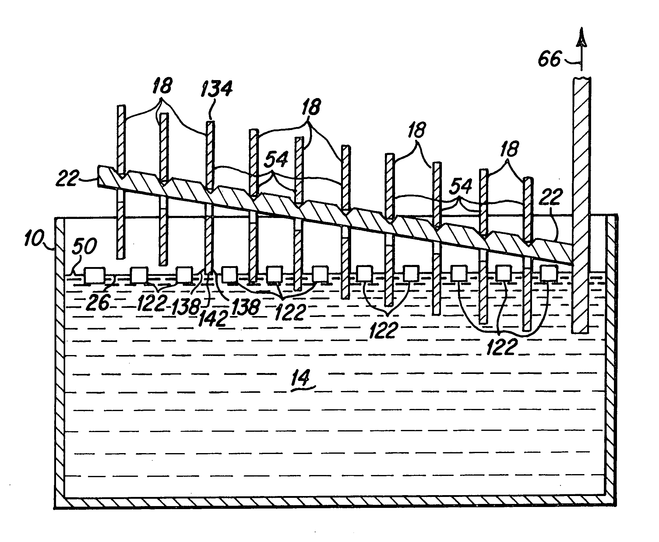
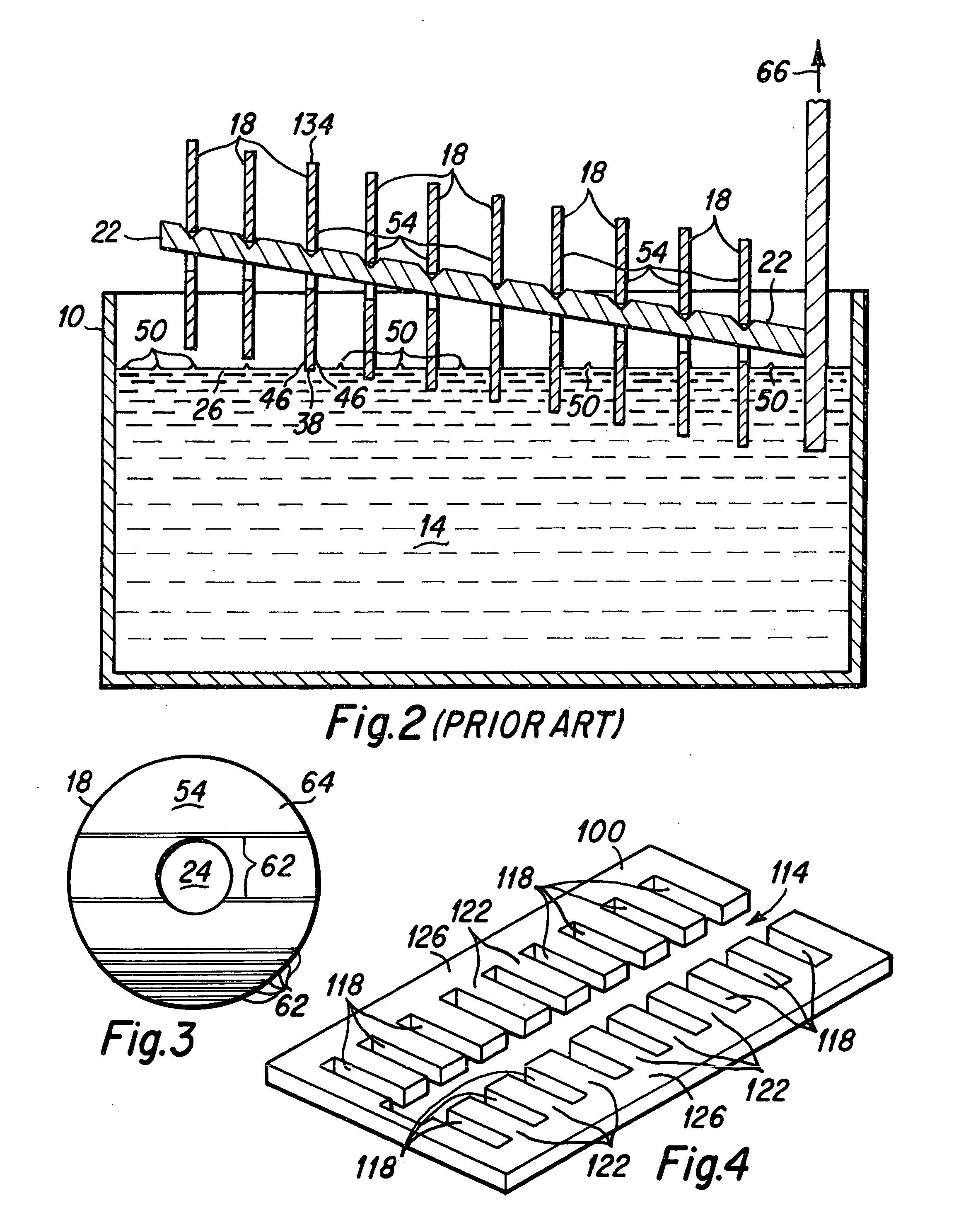
[0007] The disk lubricant tank of the present invention includes a lubricant bath cover device that resides on the lubricant bath surface to suppress surface waves. The bath cover includes a plurality of finger-like projecting members that define a plurality of disk passage slots therebetween. A plurality of disks are disposed upon a disk holding mandrel and are lowered into the lubricant bath. Each disk passes through a separate disk passage slot during the dipping process. The finger-like projections reside on the bath surface between the disk to suppress surface waves that would otherwise impinge upon side surfaces of the disk, leading to unwanted lubricant overcoat areas upon the side surfaces of the disk. Therefore, hard disks of the present invention are formed with a more uniform lubricant coating wherein unwanted lubricant overcoat areas formed by surface waves in the lubricant bath are suppressed.
[0008] It is an advantage of the disk lubricant bath device of the present invention that hard disks are manufactured with a more uniform lubricant coating.
[0009] It is another advantage of the lubricant bath device of the present invention that surface waves within the lubricant bath are suppressed.
[0010] It is a further advantage of the lubricant bath device of the present invention that a bath cover device is provided which floats on the surface of the lubricant bath to adjust to differing lubricant bath levels.
[0011] It is an advantage of a hard disk of the present invention that it is manufactured with a more uniform lubricant coating.

Problems solved by technology

The finger-like projections reside on the bath surface between the disk to suppress surface waves that would otherwise impinge upon side surfaces of the disk, leading to unwanted lubricant overcoat areas upon the side surfaces of the disk.

Method used


Image

  • Disk lubricant tank insert to suppress lubricant surface waves
  • Disk lubricant tank insert to suppress lubricant surface waves
  • Disk lubricant tank insert to suppress lubricant surface waves

Examples


Embodiment Construction

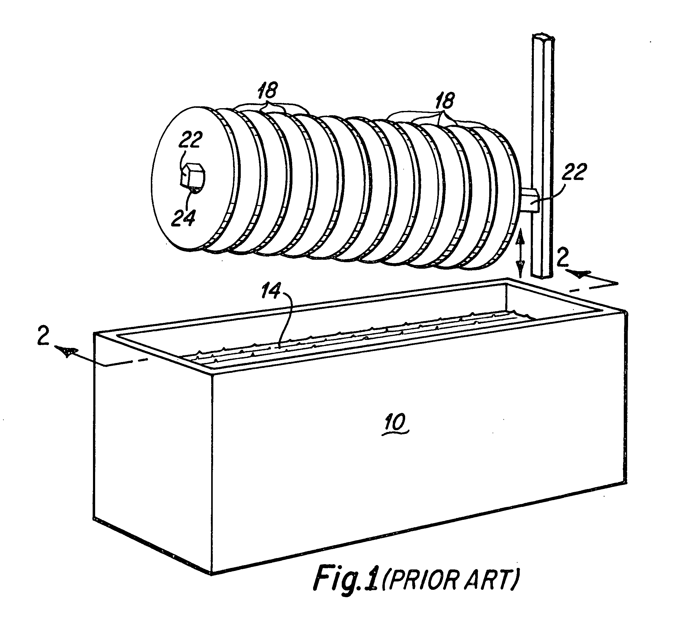
[0022] As is well known to those skilled in the art, hard disks for use in hard disk drives are coated with a thin lubrication film to protect the surface of the hard disk during hard disk drive operation. This protection is necessary where the magnetic head of the hard disk drive floats on an air bearing just a few microns above surface of the disk. Where the magnetic head, for various reasons, makes unwanted contact with the hard disk, the lubricant coating serves to minimize damage to both the hard disk surface and the surface of the magnetic head. The application upon the disk surface of a lubricant film having a uniform thickness is therefore desirable, particularly as the air bearing gap of more advanced hard disk drives is generally decreasing. However, as is next described, prior art lubricant film application techniques, specifically utilizing a lubricant tank into which the hard disks are dipped, results in a lubricant film having unwanted thickness variations. As is furth...


PUM

PropertyMeasurementUnit
lengthaaaaaaaaaa
reflectionaaaaaaaaaa
thicknessaaaaaaaaaa

Abstract

The disk lubricant tank of the present invention includes a lubricant bath cover device that resides on the lubricant bath surface to suppress surface waves. The bath cover includes a plurality of finger-like projecting members that define a plurality of disk passage slots therebetween. A plurality of disks are disposed upon a disk holding mandrel and are lowered into the lubricant bath. Each disk passes through a separate disk passage slot during the dipping process. The finger-like projections reside on the bath surface between the disk to suppress surface waves that would otherwise impinge upon side surfaces of the disk, leading to lubricant overcoat areas upon the side surfaces of the disk. Therefore, hard disks of the present invention are formed with a more uniform lubricant coating wherein unwanted lubricant overcoat areas formed by surface waves in the lubricant bath are suppressed.

Description

BACKGROUND OF THE INVENTION [0001] 1. Field of the Invention [0002] The present invention relates generally to lubricant coatings for hard disks for hard disk drives, and more particularly to devices and methods to suppress surface waves in a disk lubricant dipping tank. [0003] 2. Description of the Prior Art [0004] Hard disks that are utilized in hard disk drives are typically coated with a thin lubrication film to protect the surface of the disk during usage. A common method for applying the lubrication film to the disks is by use of a lubrication tank in which the disks are submerged in a lubricant bath and slowly withdrawn from the bath. It is desirable that the thin lubrication film form a single uniform film coating on the surface of the disk for optimum disk drive performance at the disk magnetic head interface. However, it has been found that unwanted variations in the thickness of the thin lubricant film are typically created when the lubricant film is applied utilizing the...

Claims


Application Information

Patent Timeline
Patent Type & Authority Applications(United States)
IPC IPC(8): B32B3/02B05C3/00B05C19/02B05D1/18B05C3/09
CPCY10T428/21B05C3/09
Inventor DAODANG, HUNG Q.HENDRIKS, FERDINANDWINTERLIN, LARRY W.
Owner WESTERN DIGITAL TECH INC
Learn More