PIFA with I-shaped fractal EBG structure as floor

A floor and fractal technology, applied in the direction of antenna grounding device, radiating element structure, antenna grounding switch structure connection, etc., can solve the problems of low radiation efficiency of PIFA antenna, large overall volume of antenna, etc., and achieve the suppression of antenna surface wave and backward The effect of radiation, main lobe enlargement, and back radiation reduction

Inactive Publication Date: 2014-12-03
HARBIN INST OF TECH
View PDF4 Cites 0 Cited by
  • Summary
  • Abstract
  • Description
  • Claims
  • Application Information

AI Technical Summary

Problems solved by technology

[0003] In order to solve the problem that the radiation efficiency of the existing PIFA antenna is low and the overall volume of the antenna is large, the present invention further proposes a PIFA antenna with an I-shaped fractal EBG structure as the floor

Method used


Image

  • PIFA with I-shaped fractal EBG structure as floor
  • PIFA with I-shaped fractal EBG structure as floor
  • PIFA with I-shaped fractal EBG structure as floor

Examples


specific Embodiment approach 1

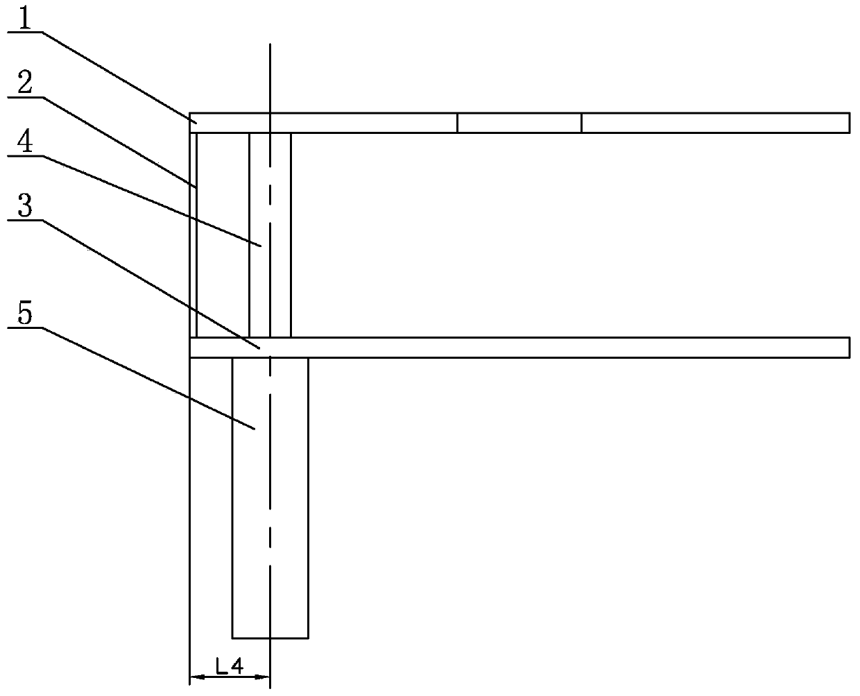
[0008] Specific implementation mode one: combine Figure 1 to Figure 5 Describe this embodiment mode, a kind of PIFA antenna with the I-shaped fractal EBG structure as the floor of this embodiment mode includes a radiation piece 1, a short circuit board 2, a floor 3, a coaxial inner conductor 4 and a coaxial outer conductor 5, and the radiation piece 1 The floor 3 is arranged side by side in parallel from top to bottom, the left end of the radiation sheet 1 is connected to the left end of the floor 3 through the short circuit board 2, the coaxial outer conductor 5 is vertically arranged below the left end of the floor 3, and coaxial The upper end of the outer conductor 5 is connected to the lower surface of the left end of the floor 3, the coaxial inner conductor 4 is vertically arranged between the radiation sheet 1 and the floor 3, and the upper end of the coaxial inner conductor 4 is connected to the lower surface of the left end of the radiation sheet 1, The lower end of t...

specific Embodiment approach 2

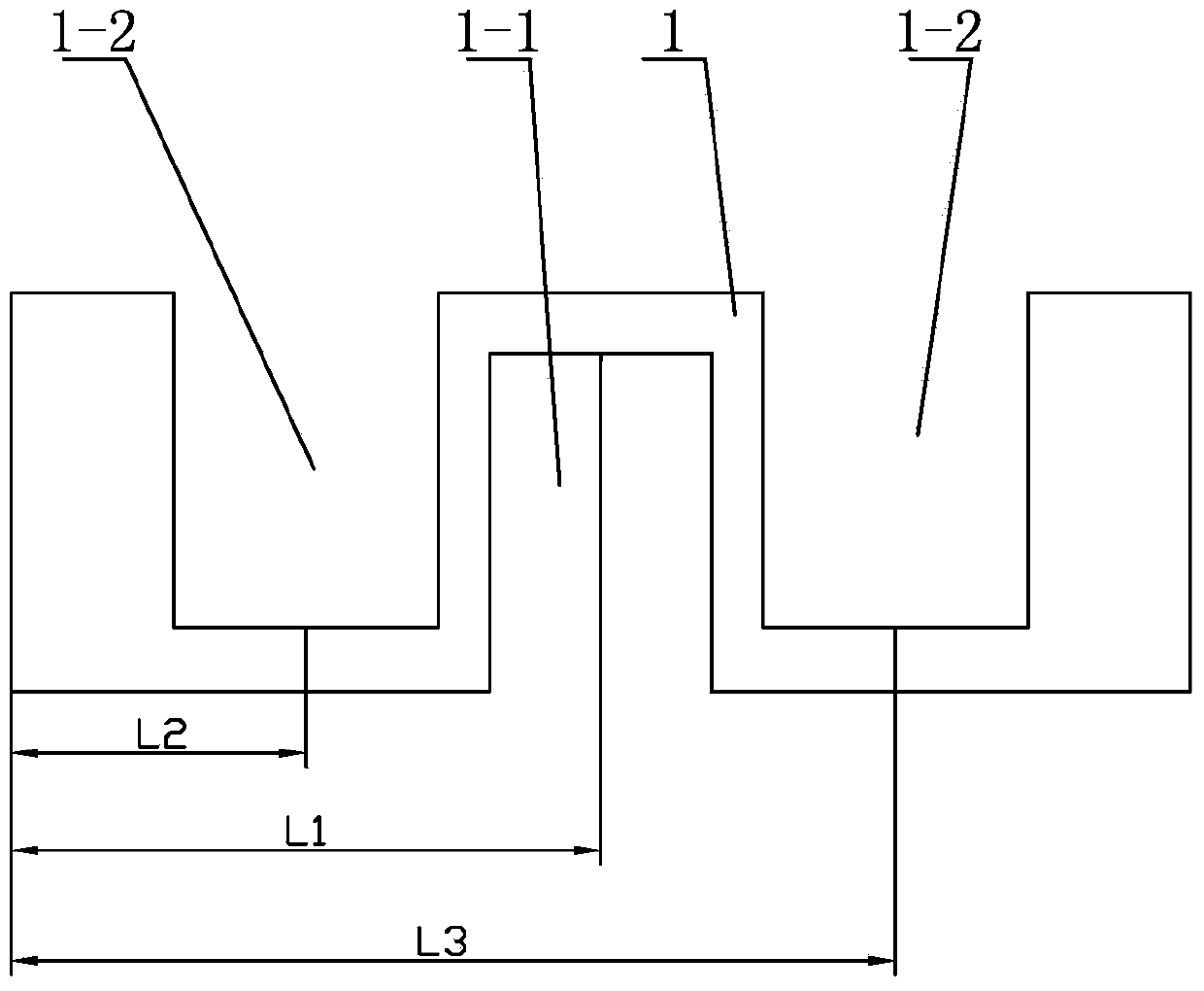
[0009] Specific implementation mode two: combination Figure 1 to Figure 3 Describe this embodiment, the length of the radiation piece 1 of the PIFA antenna of a kind of I-shaped fractal EBG structure described in this embodiment as the floor is 40mm, the width of the radiation piece 1 is 20mm, the first rectangular gap 1-1 and the radiation piece The distance L1 between the left ends of the radiation sheet 1 is 20 mm, the distance L2 between the second rectangular notch 1-2 adjacent to the left end of the radiation sheet 1 and the left end of the radiation sheet 1 is 10 mm, and the distance L2 between the second rectangular notch 1-2 at the left end of the radiation sheet 1 and the radiation sheet 1 is 10 mm. The distance L3 between the left ends of the sheet 1 is 30mm, the width of the first rectangular notch 1-1 is 9mm, the depth of the first rectangular notch 1-1 is 16mm, and the width of each second rectangular notch 1-2 is 9mm. The depth of the second rectangular notch 1...

specific Embodiment approach 3

[0011] Specific implementation mode three: combination Figure 1 to Figure 3 Describe this embodiment, the width of the short circuit board 2 of the PIFA antenna with the I-shaped fractal EBG structure as the floor in this embodiment is 2 mm, and the length of the short circuit board 2 is 10 mm.

[0012] The technical effect of this embodiment is: the arrangement makes the antenna resonate at the required frequency point, and the resonant depth is relatively deep. Other components and connections are the same as those in the first embodiment.


PUM

PropertyMeasurementUnit
Lengthaaaaaaaaaa
Widthaaaaaaaaaa
Widthaaaaaaaaaa

Abstract

The invention relates to a PIFA, in particular to a PIFA with an I-shaped fractal EBG structure as a floor. The PIFA solves the problems that an existing PIFA is low in radiation efficiency and large in overall size. The PIFA comprises a radiation sheet, a short-circuit board, a floor, a coaxial inner conductor and a coaxial outer conductor. The radiation sheet and the floor are sequentially arranged side by side in parallel from top to bottom, the left end of the radiation sheet is connected with the left end of the floor through the short-circuit board, and the coaxial outer conductor is vertically arranged below the left end of the floor. The PIFA is applied to the field of wireless communication.

Description

technical field [0001] The invention relates to a PIFA antenna, in particular to a PIFA antenna with an I-shaped fractal EBG structure as a floor, and belongs to the field of wireless communication. Background technique [0002] The radio frequency identification based on the mobile phone platform is a new technology that combines the RFID reader with the mobile phone as a mobile communication terminal, and uses RFID technology as a means to quickly obtain information through the mobile communication network platform. Since the PIFA antenna was produced, because of its small size, it can make full use of the PCB board as the ground plane, and lock the resonant length to a quarter wavelength through the ground plate. It has always been the main form of the built-in antenna. The unique frequency bandgap characteristics of the EGB (Electromagnetic Bandgap) structure make it a new type of artificial electromagnetic structure, which has a very wide range of applications in the mi...

Claims


Application Information

Patent Timeline
IPC IPC(8): H01Q1/48H01Q1/50H01Q1/36
Inventor 李红梅邢立鲲王金悦孙士明
Owner HARBIN INST OF TECH
Why Eureka
Try Eureka