Tool box

a tool box and tool technology, applied in the field of tool boxes, can solve the problems of difficult uniform spacing and alignment of individual pegs during welding process, affecting and affecting the use of the tool box user. to achieve the effect of maximizing the storage capacity of the tool box

Active Publication Date: 2006-03-30
QUALITY CRAFT INDS
View PDF9 Cites 18 Cited by
  • Summary
  • Abstract
  • Description
  • Claims
  • Application Information

AI Technical Summary

Benefits of technology

[0007] Accordingly, it is an object of the present invention to maximize the storage capability of the tool box such that numerous tools can be secured at designated locations within the box.

Problems solved by technology

These tool boxes, however, are disadvantageous because upon rough handling of the tool box or possible inversion of the tool box, the tools disposed in designated channels or areas become displaced and scattered throughout the tool box.
While adding individual lids to the compartments in a tool box can help prevent the intermingling of tools when the tool box is handled or inverted, such compartments, however, normally inhibit the tool box user from finding the appropriate tool when the main tool box cover is open.
However, uniformly spacing and aligning the individual pegs during the welding process is difficult as both the pegs and plates tend to deform from the heat of the welder.

Method used


Image

  • Tool box
  • Tool box
  • Tool box

Examples


Embodiment Construction

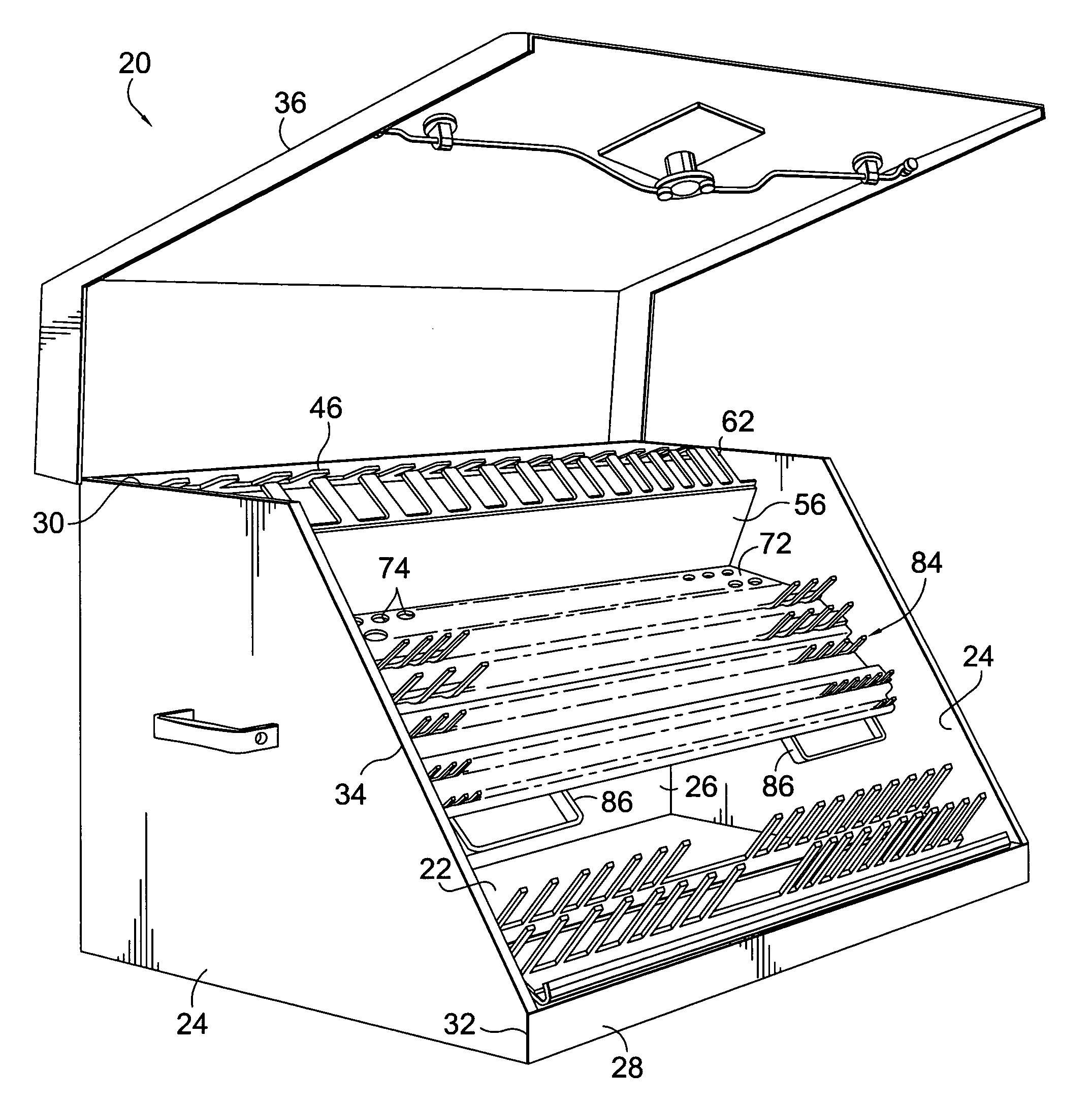
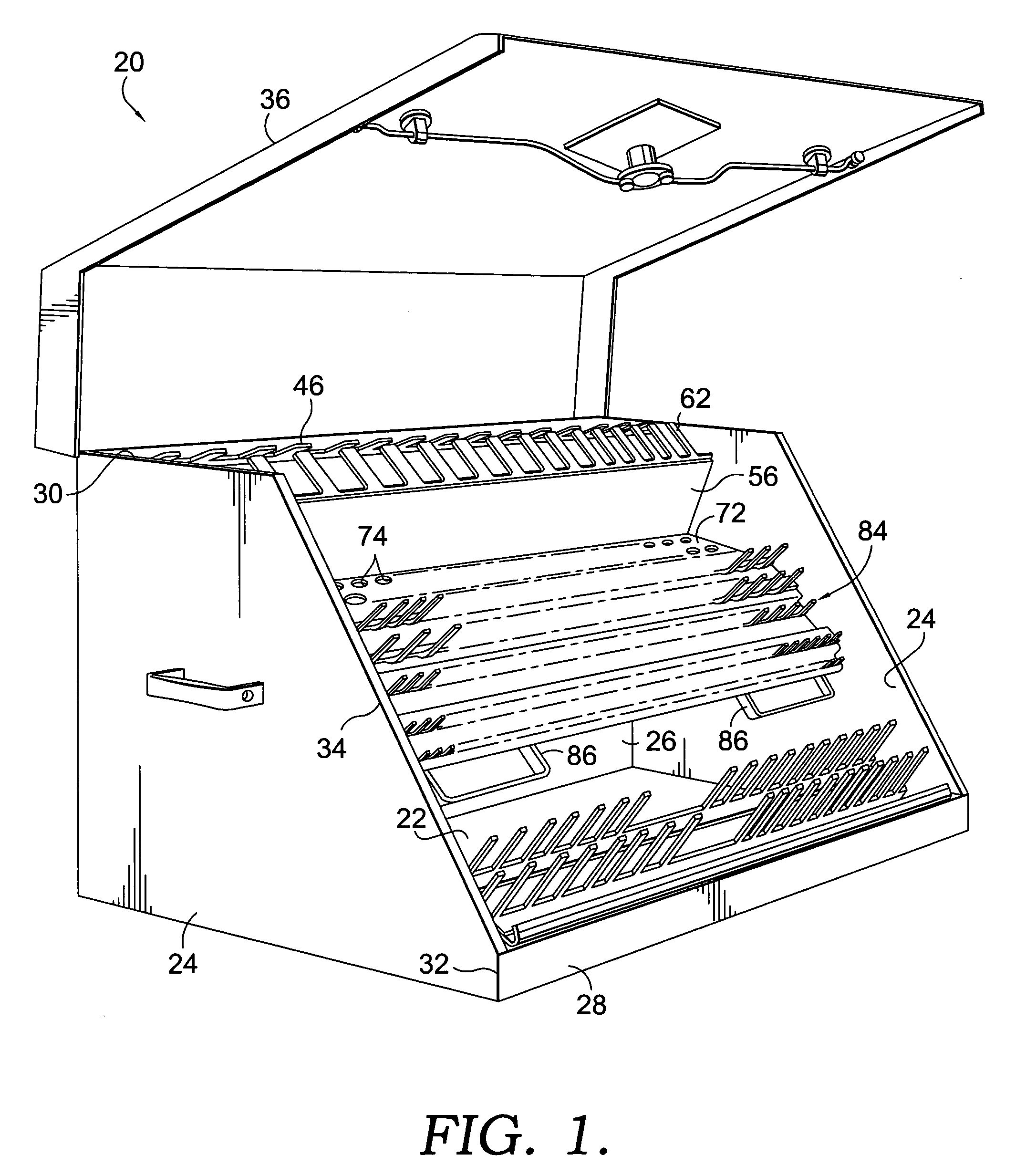
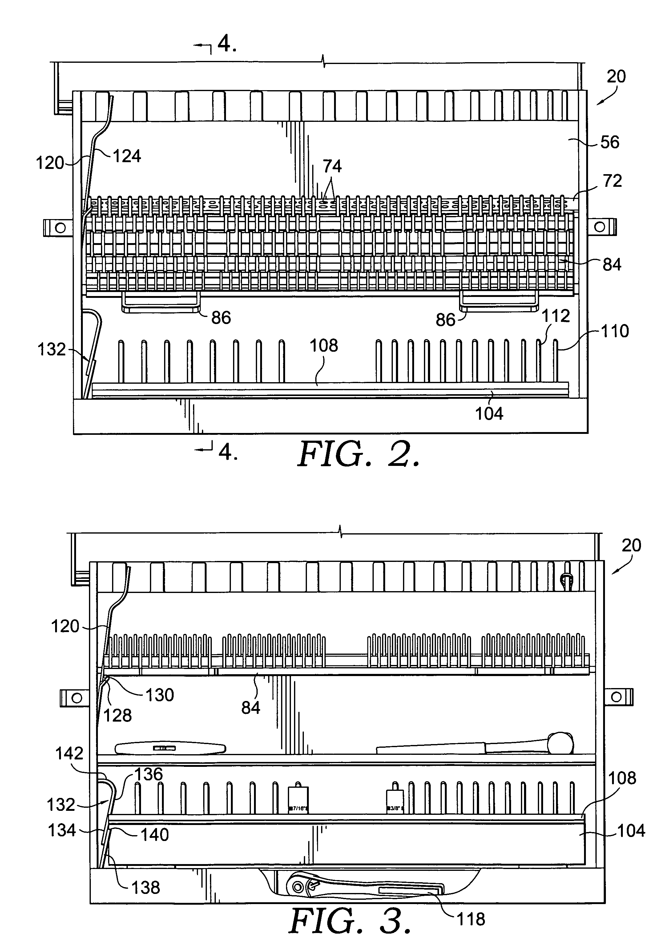
[0030] With reference to FIGS. 1 and 4, tool box 20 constructed in accordance with the present invention is shown. Tool box 20 has a bottom portion 22, a pair of side portions 24 extending upwardly from bottom portion 22, a back portion 26 extending upwardly from bottom portion 22, and a front portion 28 extending upwardly from bottom portion 22. Side portions 24 each have an upper horizontal edge 30 and a front vertical edge 32. Upper edge 30 and front edge 32 are connected by a downwardly sloping slanted edge 34. Thus, bottom portion 22, side portions 24, back portion 26, and front portion 28 define an expanse in which tools or other items can be stored.

[0031] With additional reference to FIG. 7, a cover 36 is attached to back portion 26 at a location near upper edge 38 of back portion 26. Cover 36 is attached to back portion 26 by a hinge structure 40 such that cover 36 is rotatable between an open position, illustrated in FIG. 1, and a closed position, illustrated in FIG. 7. Co...


PUM


Abstract

A tool box has a bottom portion, a pair of side portions, a back portion, a front portion, and a cover rotatably mounted adjacent the back portion. The cover has a horizontal section and a slanted section sloping downwardly from the horizontal section. A partition plate is positioned in the interior of the tool box and has a peg sheet mounted thereto with a row of pegs extending upwardly from the top of the partition plate. The upper ends of the pegs contact or are in close proximity to the horizontal section of the cover when the cover is in its closed position such that tools disposed on the pegs are secured in position. A pair of compartments are positioned in the interior, one near the bottom of the box and one intermediate the bottom and the top, both having a cover structure disposed thereon with peg sheets for maintaining tools in secured and unsecured positions.

Description

CROSS-REFERENCE TO RELATED APPLICATIONS [0001] Not applicable. STATEMENT REGARDING FEDERALLY SPONSORED RESEARCH OR DEVELOPMENT [0002] Not applicable. BACKGROUND OF THE INVENTION [0003] Numerous containers or boxes are known in the prior art for arranging tools of different shapes and sizes within a tool box. For instance, tool boxes sometimes have trays with longitudinal channels therein in which sockets for use with a ratchet drive are placed. Further, tool boxes with compartments in their interior for containing different sizes or structures of tools are known. These tool boxes, however, are disadvantageous because upon rough handling of the tool box or possible inversion of the tool box, the tools disposed in designated channels or areas become displaced and scattered throughout the tool box. [0004] While adding individual lids to the compartments in a tool box can help prevent the intermingling of tools when the tool box is handled or inverted, such compartments, however, normal...

Claims


Application Information

Patent Timeline
Patent Type & Authority Applications(United States)
IPC IPC(8): B65D85/28
CPCB25H3/02B25H3/003
Inventor SCHMIDT, LAVERN D.KOEHN, VINCENT G.
Owner QUALITY CRAFT INDS
Why Eureka
Try Eureka