
Electrochemical method for the removal of PPM levels of carbon monoxide from hydrogen for a fuel cell

a fuel cell and carbon monoxide technology, applied in the direction of electrolysis components, electrochemical generators, electrolysis processes, etc., can solve the problems of current available technologies, difficult to remove low level co from hsub>2 /sub>rich stream to less than 10 ppm, and degradation of fuel cell performance and durability, etc., to achieve the effect of increasing the performance and durability of pem fuel cells

Inactive Publication Date: 2016-02-16
UNIV OF CENT FLORIDA RES FOUND INC
View PDF5 Cites 2 Cited by
  • Summary
  • Abstract
  • Description
  • Claims
  • Application Information

AI Technical Summary

Benefits of technology

The technical effects of this patent are to create a catalyst that can absorb and oxidize CO efficiently, allowing for more effective storage in batteries and fuel cells. Additionally, the invention aims to remove CO from the H2 fuel stream to improve the performance and durability of fuel cells.

Problems solved by technology

Just 10 ppm of CO in H2 fuel stream can cause degradation in the performance and durability of fuel cells.
The on-board removal of low level CO from H2 rich stream to less than 10 ppm is a challenging task.
The current available technologies are precluded from applicability because of their high cost, poor selectivity, and elevated temperature and pressure requirements.
In addition, these technologies suffer from significant H2 loss.
This low concentration of CO in the H2 outlet stream from WGS can not be avoided and a deep removal process is required.
The prior art technologies for the on-board removal of CO for automotive applications have limitations.
Pd-based membrane purification method is expensive and requires both high operating temperature and a high-pressure differential.
Therefore, it is not suitable for on board applications.
However, its disadvantages are the consumption of H2 and the requirement of high temperature.
In this oxidation process, part of H2 is oxidized to produce water resulting in a fuel loss.
However, it is should be noted that it is difficult for any of these three methods to completely remove CO because, fundamentally, the ppm level of CO is thermodynamically stable in an H2 stream at ambient conditions.
However, increasing the PEM fuel cell operating temperature might have some adverse impacts on fuel cell performance.
Firstly, higher operating temperature greatly increases the resistance of the Nafion® membrane, resulting in a reduction of fuel cell performance.
When temperature is above 100° C., maintaining high humidity for a PEM fuel cell requires a system pressure greater than 1 atm, which again reduces the efficiency of the fuel cell.
Secondly, operating a PEM fuel cell at temperature greater than 100° C. will enhance the aggregation rate of Pt particles as well as the Pt dissolution in the fuel cell electrocatalyst layer, both of which decrease the performance of the cell.
Finally, above 100° C. PEM fuel cells suffer a higher rate of membrane degradation, shortening their long-term stability.
However, since the H2 combustion limit is only 5% of O2 in the H2 stream, a malfunction of the O2 inlet flow could result in very undesirable consequences.
Also, as indicated in literature, air-bleeding technology is only effective at a very low CO level (i.e. less than 50 ppm) and at low H2 flow rates.
Therefore, air-bleeding technology is unlikely to be suitable for on-board CO removal in a PEM fuel cell system.
It has been found that adding Ru, Rh or Ir catalysts to the Pt anode reduces CO poisoning, but it can not fundamentally eliminate CO poisoning.
Furthermore, at an 80° C. fuel cell operating temperature the Pt alloy method is unable to completely resolve the CO poisoning issue.

Method used


Image

  • Electrochemical method for the removal of PPM levels of carbon monoxide from hydrogen for a fuel cell
  • Electrochemical method for the removal of PPM levels of carbon monoxide from hydrogen for a fuel cell
  • Electrochemical method for the removal of PPM levels of carbon monoxide from hydrogen for a fuel cell

Examples


Embodiment Construction

[0045]Before explaining the disclosed embodiments of the present invention in detail it is to be understood that the invention is not limited in its application to the details of the particular arrangements shown since the invention is capable of other embodiments. Also, the terminology used herein is for the purpose of description and not of limitation.

[0046]The following is a partial list of abbreviations used throughout the application:

PEM polymer electrolyte membrane

WGS water gas shift

EWGS electrochemical water gas shift

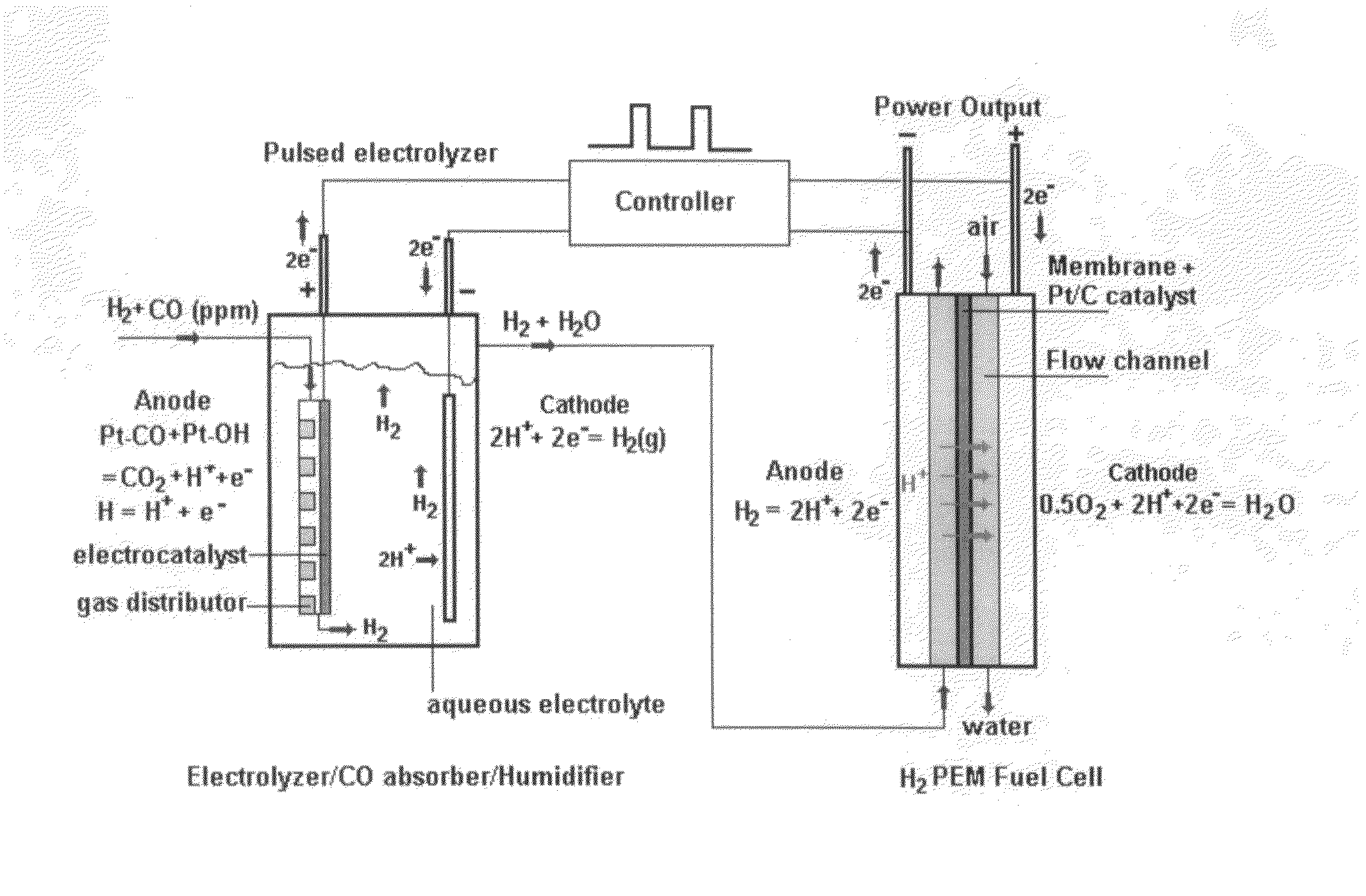
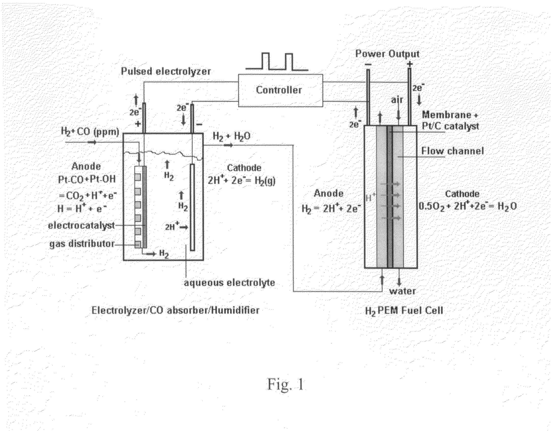
[0047]Carbon monoxide (CO) in hydrogen (H2) stream can cause severe performance degradation for an H2 polymer electrolyte membrane (PEM) fuel cell. The on-board removal of CO from a H2 stream requires a removal process temperature less than 80° C., and a fast removal reaction rate in order to minimize the reactor volume. At the present time, few technologies have been developed that meet these two requirements. The present invention describes an electrochemical w...


PUM

PropertyMeasurementUnit
electrical currentaaaaaaaaaa
volumeaaaaaaaaaa
temperatureaaaaaaaaaa

Abstract

An electrochemical water gas shift system for removing low level carbon monoxide from hydrogen stream. The system including an electrolyzer having a porous anode for absorbing carbon monoxide from a hydrogen stream as a feed stream for a polymer electrolyte membrane fuel cell for generating an electrical energy, a small portion of electricity generated by the fuel cell is applied to the electrolyzer to convert carbon monoxide adsorbed in the porous anode to carbon dioxide and hydrogen via an electrochemical gas shift reaction without oxygen or air input. In an embodiment, the system includes a first electrolyzer operating as a CO adsorber and a second electrolyzer connected in parallel with the first electrolyzer operating as a CO remover. Two electrolyzers can be operated alternatively as CO adsorber and CO remover.

Description

[0001]This application claims the benefit of priority of U.S. Provisional Application No. 60 / 789,302 filed on Mar. 5, 2006.FIELD OF THE INVENTION[0002]This invention relates to removal of carbon monoxide from hydrogen stream and, in particular, to methods, systems, apparatus and devices using an electrochemical method for on-board deep removal of low level carbon monoxide and other impurities from hydrogen streams for a polymer electrolyte membrane fuel cell applications.BACKGROUND AND PRIOR ART[0003]Carbon monoxide (CO) is one of the most common impurities in hydrogen (H2) streams that have a great negative impact on the performance and durability of polymer electrolyte membranes (PEM). Just 10 ppm of CO in H2 fuel stream can cause degradation in the performance and durability of fuel cells. The on-board removal of low level CO from H2 rich stream to less than 10 ppm is a challenging task. The current available technologies are precluded from applicability because of their high cos...

Claims


Application Information

Patent Timeline
Patent Type & Authority Patents(United States)
IPC IPC(8): H01M8/06H01M8/04H01M8/10
CPCH01M8/0668H01M8/1018H01M8/0675H01M8/0662H01M8/04126C25B1/00C25B1/02C25B15/08H01M16/00H01M2008/1095Y02E60/50
Inventor HUANG, CUNPINGJIANG, RUICHUNELBACCOUCH, MOHAMEDMURADOV, NAZIMFENTON, JAMES M.
Owner UNIV OF CENT FLORIDA RES FOUND INC
Learn More