
Camera assemblies having overlapping rocker and link projections

Inactive Publication Date: 2006-03-30
MONUMENT PEAK VENTURES LLC
View PDF6 Cites 0 Cited by
  • Summary
  • Abstract
  • Description
  • Claims
  • Application Information

AI Technical Summary

Benefits of technology

[0010] It is an advantageous effect of the invention that improved camera assemblies and methods are provided, in which a linkage is blocked from pivoting a rocker and lens turret.
that improved camera assemblies and methods are provided, in which a linkage is blocked from pivoting a rocker and lens turret.

Problems solved by technology

This functionality is relatively easy to provide using costly mechanisms having close tolerances, but is more difficult using inexpensive mechanisms.
A turret and connected over-center mechanism having such tolerances present a risk of tilting out-of-plane during switching between different lens positions.
Such tilting can be caused by an inexact over-center biasing that tips the turret out-of-plane while urging the turret toward one or both lens positions.
Countering the tilt by use of a strong retention spring runs the risk of stalling the turret.
Another risk of tilting can be presented by the use of a long lever to switch a lens turret.

Method used


Image

  • Camera assemblies having overlapping rocker and link projections
  • Camera assemblies having overlapping rocker and link projections
  • Camera assemblies having overlapping rocker and link projections

Examples


Embodiment Construction

[0027] The term “fixed” and like terms are used herein in the sense of a physical position or relationship that is in immobile and unchanging.

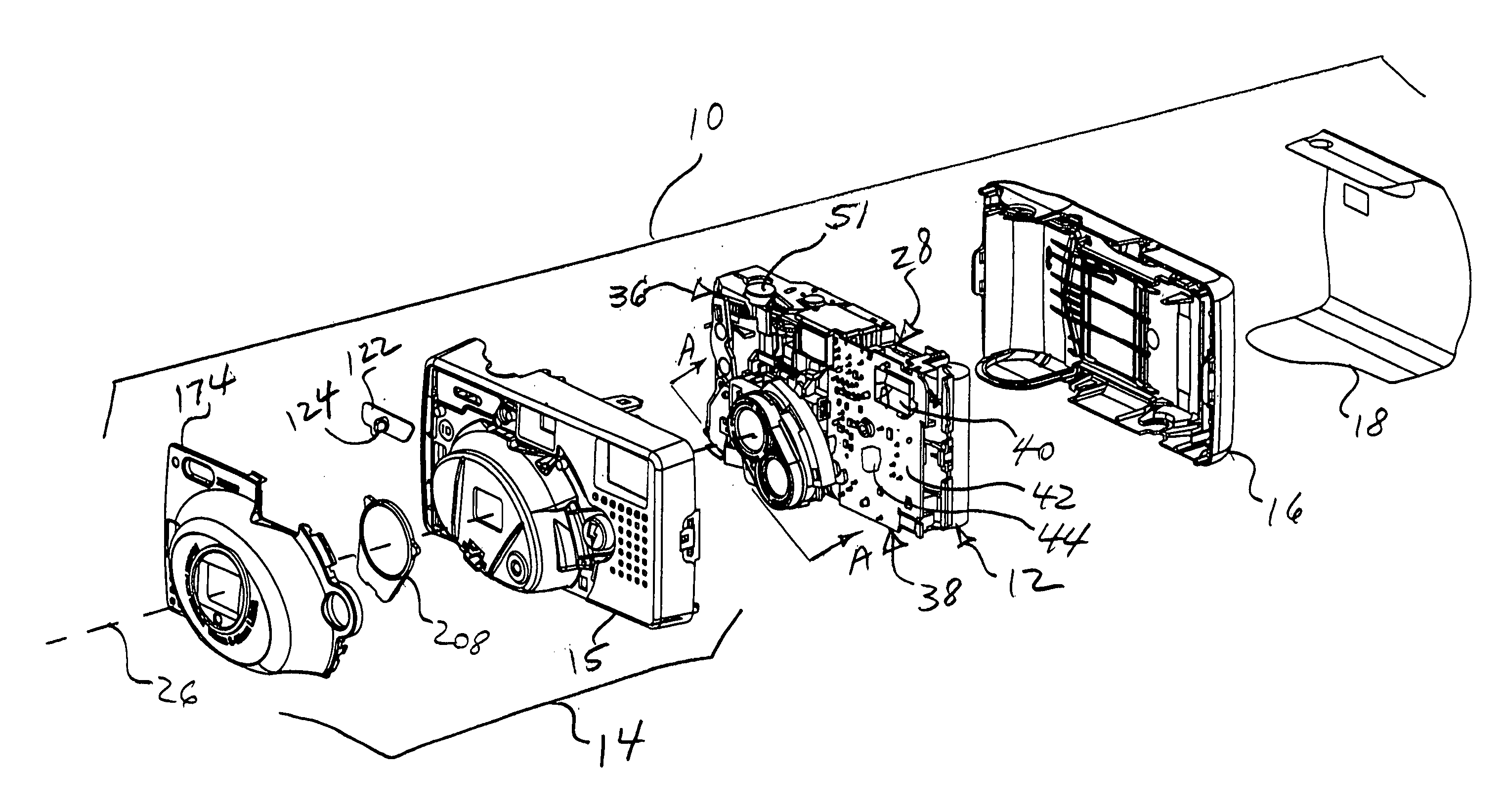
[0028] The term “camera assembly” is used here to refer to a complete camera or an incomplete subunit of a camera that can be assembled with other parts to form a complete camera. The term “camera assembly” is inclusive of a complete one-time use camera and of a subassembly of a one-time-use camera. The usage of “camera” in the term “camera assembly” does not limit possible uses of a particular camera assembly. For example, a “camera assembly” that includes a lens system is inclusive of the usage of the same assembly as a component of binoculars. For convenience, camera assemblies are generally designated by more descriptive names related to respective functions in a completed camera.

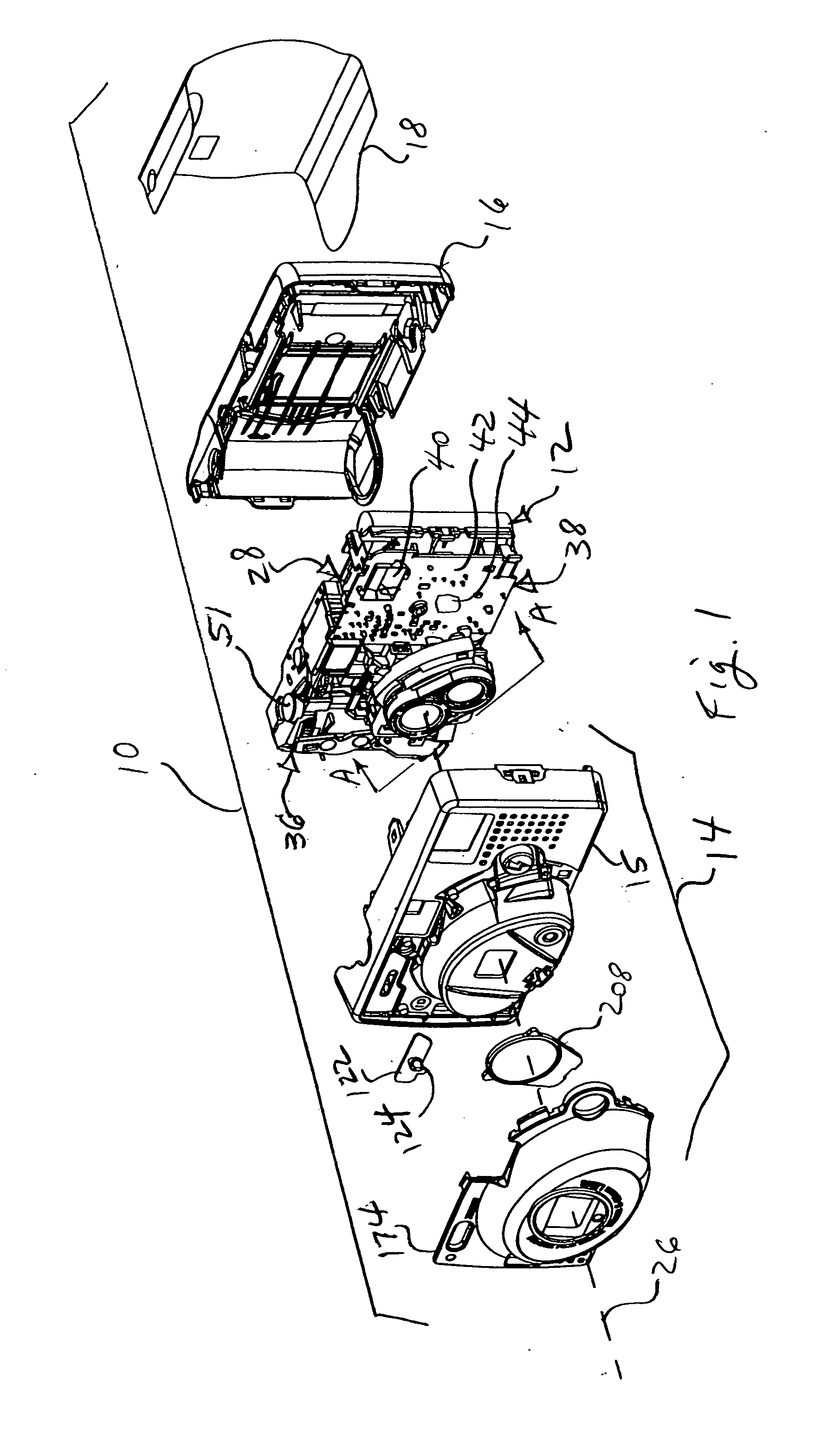
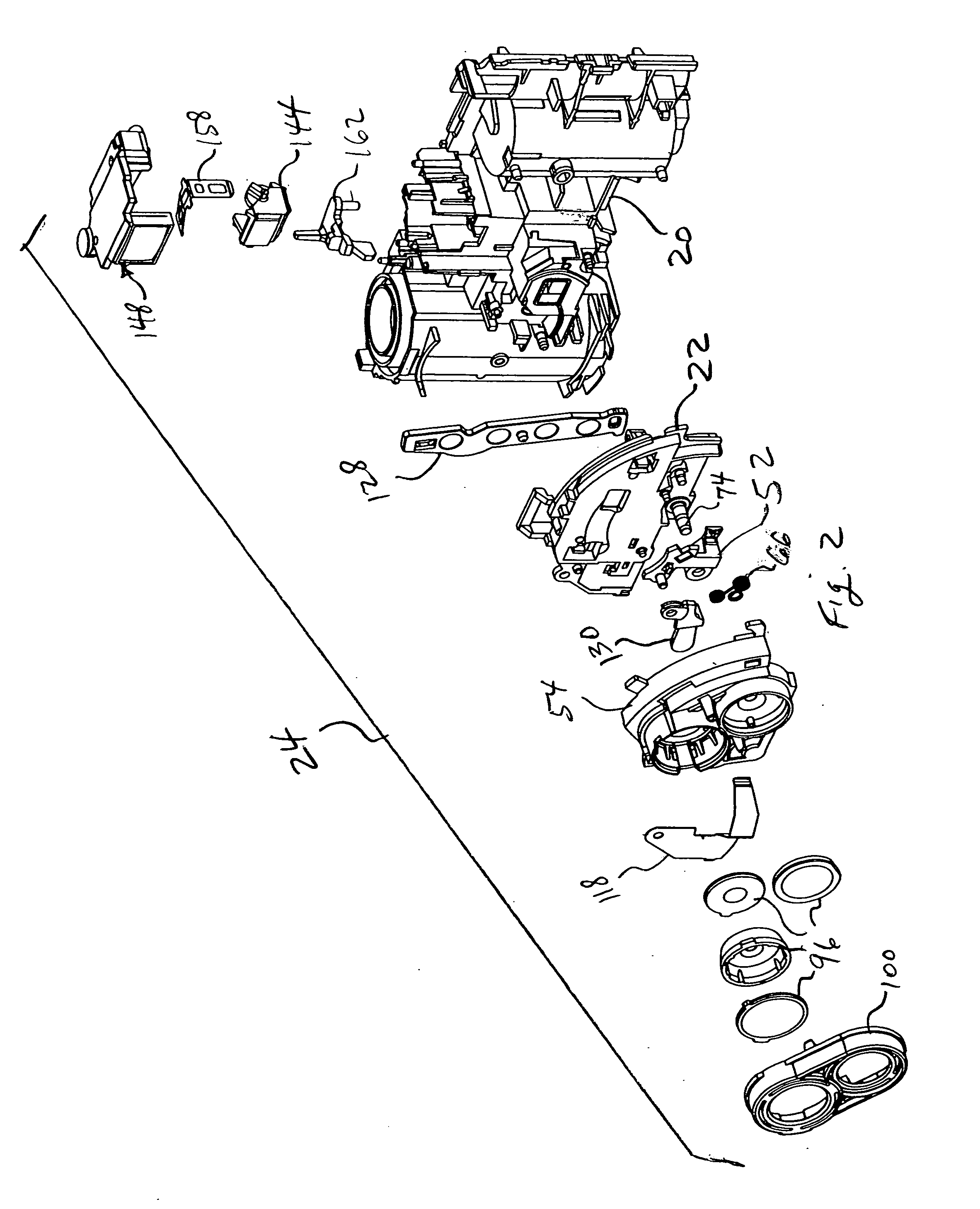
[0029] Turning now particularly to FIGS. 1-6, the camera 10 has a main member 12 held within a shell having a front cover assembly 14 and a rear cover 16. The f...


PUM


Abstract

A camera assembly has a main member having a mount defining an optical axis. A rocker supported by the mount, is pivotable between first and second positions. First and second taking lenses are movable by the rocker between a first configuration, in which the optical axis intersects the first lens and a second configuration, in which the optical axis intersects the second lens. A linkage is switchable between first and second conformations to pivot the rocker. The linkage includes an inner link having an inner end rotatably joined to the rocker. The inner end and rocker have overlapping projections holding them in alignment relative to a plane perpendicular to the optical axis.

Description

CROSS REFERENCE TO RELATED APPLICATIONS [0001] Reference is made to commonly assigned, co-pending U.S. patent application Ser. No. ______, [Attorney Docket No. 88376RLW], entitled: CAMERA ASSEMBLY HAVING LENS TURRET AND INDEPENDENTLY MOVABLE ROCKER filed Sep. 24, 2004, in the names of Anthony DiRisio, Thomas S. Albrecht, Michael L. Wirt, Michael A. Litzenberger, Douglas H. Pearson, and Joel S. Lawther; Ser. No. ______. [0002] Reference is made to commonly assigned, co-pending U.S. patent application Ser. No. ______, [Attorney Docket No. 88831RLW], entitled: CAMERA GUARD WITH BEZEL AND RING, filed Sep. 24, 2004, in the names of James G. Rydelek, Sunny C. Kim and John M. Staton; Ser. No. ______.FIELD OF THE INVENTION [0003] The invention relates to photography and photographic cameras and more particularly relates to camera assemblies having overlapping rocker and link projections. BACKGROUND OF THE INVENTION [0004] Cameras have long used turrets to switch mounted lenses. Turrets allo...

Claims


Application Information

Patent Timeline
IPC IPC(8): G03B17/00
CPCG03B17/00
Inventor DIRISIO, ANTHONY
Owner MONUMENT PEAK VENTURES LLC
Learn More