Electrodeless lamp with incorporated reflector

Inactive Publication Date: 2006-04-06
LEDVANCE LLC
View PDF11 Cites 4 Cited by
  • Summary
  • Abstract
  • Description
  • Claims
  • Application Information

AI Technical Summary

Benefits of technology

[0009] It is another object of the invention to enhance the usability of HOELs.
[0010] These objects are accomplished, in one aspect of the invention, by the provision of an electrodeless lamp comprising; a closed-loop, tubular lamp envelope containing

Problems solved by technology

Fluorescent lamps emit light in all directions; however, in most applications that is not desirable and more than 50% of the light can be wasted.
To increase the efficiency and achieve better light control the reflector has to be placed farther away from the lamp; however, this results in a larger fixture.
As the si

Method used


Image

  • Electrodeless lamp with incorporated reflector
  • Electrodeless lamp with incorporated reflector
  • Electrodeless lamp with incorporated reflector

Examples


Example

[0016] For a better understanding of the present invention, together with other and further objects, advantages and capabilities thereof, reference is made to the following disclosure and appended claims taken in conjunction with the above-described drawings.

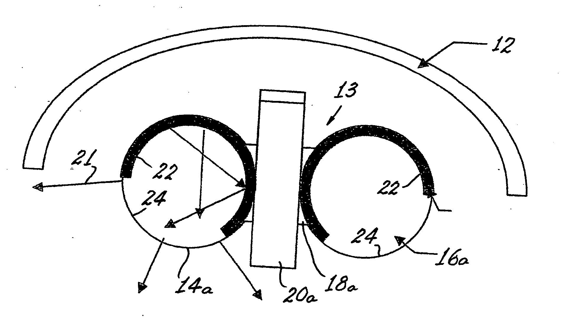
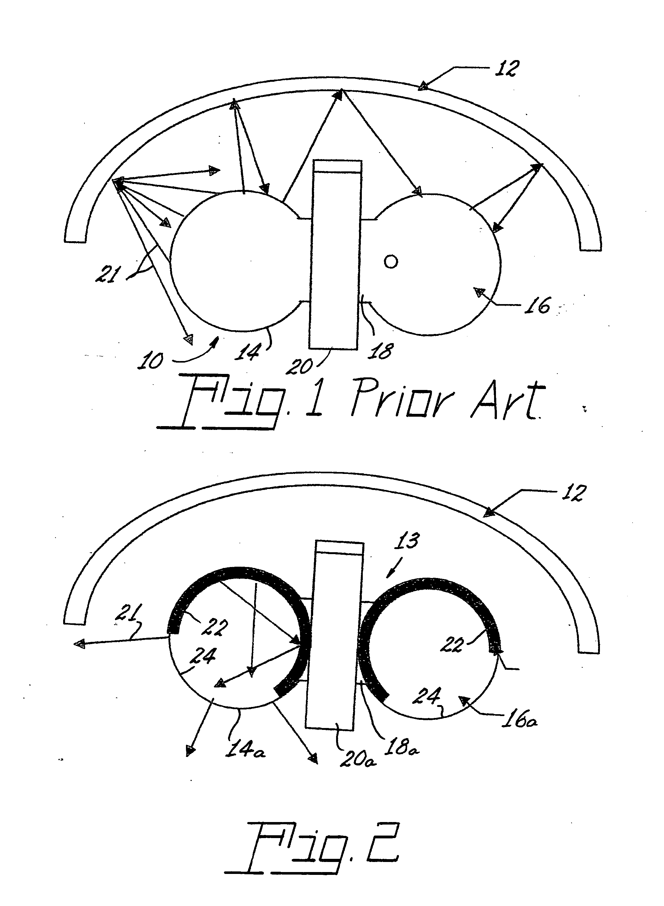
[0017] Referring now to the drawings with greater particularity, there is shown in FIG. 1 a high output electrodeless lamp (HOEL) 10 mounted adjacent a reflector 12. The lamp 10 comprises parallel cylindrical glass tubes 14, 16, connected at each end by a tube 18. The tubes 18 are surrounded by magnetic toroids 20, as is known. The rectangular shape of the HOEL does not mimic a point source as do most incandescent and arc discharge lamps so that attempts to retrofit an HOEL to a conventional reflector or existing fixture leads to poor light control as shown in FIG. 1, where much of the light emitted by the lamp 10 (illustrated by arrows 21) hits the reflector 12 and is absorbed by the lamp itself instead of being directed outwa...


PUM


Abstract

An electrodeless lamp (10a), wherein the lamp comprises a closed-loop, tubular lamp envelope (13) with parallel cylindrical glass tubes (14a 16a) containing an arc generating and sustaining medium, means (20a) in the form of magnetic toroids for energizing the medium; and a reflector coating (22) associated with the envelope (13) and affixed thereto. In a preferred embodiment of the invention the reflector coating (22) is on the internal surface (24) of the envelope and comprises a layer of a reflective m, such as alumina. Alternatively, the reflective coating (22) can be applied to the external surface of the envelope.

Description

RELATED APPLICATIONS [0001] This application claims priority based on U.S. Provisional Application Ser. No. 60 / 616,371 filed Oct. 6, 2004, entitled Electrodeless Fluorescent Lamp With Incorporated Reflector For General Lighting Applications.TECHNICAL FIELD [0002] This invention relates to electrodeless fluorescent lamps and more particularly to such lamps having a reflector intimately associated with the lamp envelope. BACKGROUND ART [0003] Fluorescent lamps emit light in all directions; however, in most applications that is not desirable and more than 50% of the light can be wasted. In order to increase the coefficient of light utilization, fixtures employing reflectors are used. [0004] The reflectors are used to recover light that would otherwise be lost (backward lighting), as well as to direct the light where needed (light control). [0005] The reflector design depends upon the application and on lamp geometry and size. The smaller the light source the smaller the reflector and t...

Claims


Application Information

Patent Timeline
IPC IPC(8): H01J1/62F21Y101/00
CPCH01J61/35H01J65/042H01J65/04
Inventor MARTIN, ROBERTTETREAULT, ALINEDUTTA, ARUNAVAMARIAN, DANIEL
Owner LEDVANCE LLC
Why Eureka
Try Eureka